Inductance of a Coil
Inductance of a Coil: Complete Guide to Factors, Formula, and Self-Inductance
Introduction to the Inductance of a Coil
In the Inductor article, we explored the physical component known as the inductor and its fundamental ability to oppose changes in current. But how do we quantify this ability? How do we calculate exactly how much opposition a specific coil will provide? The answer lies in the property known as inductance.
Inductance is the inherent property of a coil (or any conductor) that determines its ability to generate a magnetic flux for a given amount of current, and consequently, its ability to induce a voltage when that current changes. It is the electrical equivalent of mechanical mass or inertia. Just as a heavier object requires more force to change its speed, a coil with higher inductance requires more voltage to change its current.
Understanding the inductance of a coil is critical for electrical engineers and technicians. Whether you are winding a custom transformer, selecting a choke for a power supply, or designing a radio frequency (RF) filter, you must know how the physical dimensions and materials of a coil dictate its electrical behavior. This comprehensive guide will break down the physics of self-inductance, the four primary factors that affect a coil’s inductance, the mathematical formulas used to calculate it, and the real-world imperfections of physical coils.
What is the Inductance of a Coil?
The inductance of a coil is a measure of its ability to store energy in a magnetic field and oppose changes in current. It is measured in Henrys (H). One Henry is defined as the inductance that induces one volt of electromotive force (EMF) when the current through the coil changes at a rate of one ampere per second.
The Physics of Self-Inductance
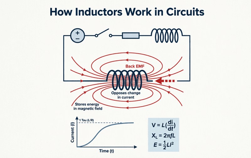
When we talk about the “inductance of a coil,” we are specifically referring to self-inductance. This is the phenomenon where a changing current in a coil induces a voltage in that same coil.
How Self-Induction Occurs
- Current Flow: When an alternating current (or a changing DC current) flows through a coil, it generates a magnetic field.
- Flux Linkage: The magnetic field lines (magnetic flux) expand and collapse, cutting across the individual turns of the coil itself.
- Induced EMF: According to Faraday’s Law of Electromagnetic Induction, this changing magnetic flux induces an electromotive force (EMF) in the coil.
- Opposition (Lenz’s Law): According to Lenz’s Law, the polarity of this induced EMF is such that it opposes the change in current that created it. This is why it is often called Back EMF or Counter EMF.
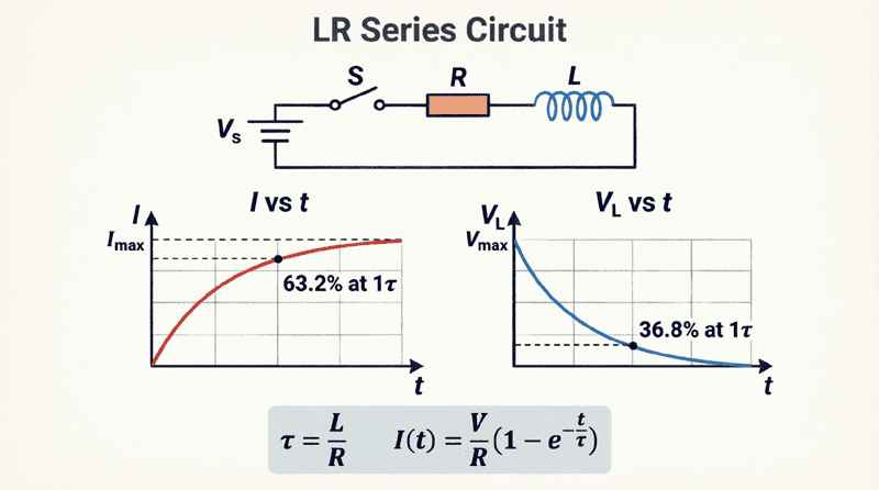
The magnitude of this self-induced EMF is directly proportional to the rate at which the current is changing, and the constant of proportionality is the inductance ($L$) of the coil.
What is Self-Inductance?
Self-inductance is the property of a coil to induce a voltage in itself when the current flowing through it changes. This induced voltage (Back EMF) always opposes the change in current, acting as electrical inertia.
Factors Affecting the Inductance of a Coil
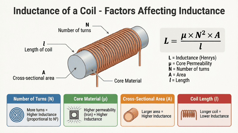
The inductance of a coil is not a random number; it is strictly determined by its physical construction. If you want to increase or decrease the inductance of a coil, you must alter one of four primary physical parameters:
1. Number of Turns ($N$)
The most significant factor is the number of turns of wire in the coil. The inductance is proportional to the square of the number of turns ($N^2$).
- If you double the number of turns, the inductance increases by a factor of four ($2^2 = 4$).
- If you triple the turns, the inductance increases by a factor of nine ($3^2 = 9$).
Why? More turns mean more wire cutting the magnetic flux, and the magnetic field itself is stronger because it is generated by more loops of current.
2. Cross-Sectional Area ($A$)
The inductance is directly proportional to the cross-sectional area of the coil’s core.
- A larger area allows more magnetic flux lines to pass through the center of the coil.
- If you double the cross-sectional area, the inductance doubles.
3. Length of the Coil ($l$)
The inductance is inversely proportional to the physical length of the coil.
- If you stretch a coil out, making it longer while keeping the number of turns the same, the magnetic flux becomes less concentrated, and the inductance decreases.
- A tightly wound, short coil will have a much higher inductance than a long, stretched-out coil with the same number of turns.
4. Permeability of the Core Material ($\mu$)
The material inside the coil dramatically affects its inductance. This property is called magnetic permeability ($\mu$), which is a measure of how easily a material can support the formation of a magnetic field.
- Air/Vacuum: Has a baseline permeability ($\mu_0$).
- Ferromagnetic Materials (Iron, Ferrite): Have a much higher relative permeability ($\mu_r$). Inserting an iron core into an air-core coil can increase its inductance by hundreds or even thousands of times.
The Inductance Formula
By combining the four factors mentioned above, we can calculate the approximate inductance of a long, straight solenoid (a standard cylindrical coil) using the following formula:
$L = \frac{N^2 \mu A}{l}$
Where:
- $L$ = Inductance in Henrys (H)
- $N$ = Total number of turns of wire
- $\mu$ = Permeability of the core material in Henrys per meter (H/m). ($\mu = \mu_0 \times \mu_r$, where $\mu_0 = 4\pi \times 10^{-7}$ H/m for air/vacuum).
- $A$ = Cross-sectional area of the coil in square meters ($m^2$)
- $l$ = Length of the coil in meters (m)
Practical Calculation Example
Problem: Calculate the inductance of an air-core coil with 200 turns, a length of 0.1 meters, and a cross-sectional area of 0.001 $m^2$.
Solution:
Given:
- $N = 200$
- $l = 0.1$ m
- $A = 0.001$ $m^2$
- $\mu = \mu_0 = 4\pi \times 10^{-7} \approx 1.257 \times 10^{-6}$ H/m
$L = \frac{200^2 \times (1.257 \times 10^{-6}) \times 0.001}{0.1}$
$L = \frac{40,000 \times 1.257 \times 10^{-9}}{0.1}$
$L = \frac{5.028 \times 10^{-5}}{0.1}$
$L = 5.028 \times 10^{-4}$ H = 0.5028 mH (millihenrys)
What is the formula for the inductance of a coil?
The inductance of a coil is calculated using the formula $L = \frac{N^2 \mu A}{l}$, where N is the number of turns, $\mu$ is the core permeability, A is the cross-sectional area, and l is the length of the coil. Inductance increases with more turns, larger area, and higher permeability, but decreases as the coil gets longer.
Calculating Self-Induced EMF
While the formula above calculates the physical property of inductance based on construction, we also need to know how much voltage the coil will actually induce when operating in a circuit. This is governed by Faraday’s Law, expressed mathematically as:
$e = -L \frac{di}{dt}$
Where:
- $e$ = Self-induced electromotive force (EMF) in volts (V)
- $L$ = Inductance of the coil in Henrys (H)
- $\frac{di}{dt}$ = Rate of change of current in amperes per second (A/s)
- The negative sign (-) = Indicates that the induced EMF opposes the change in current (Lenz’s Law).
Understanding the Rate of Change ($\frac{di}{dt}$)
The induced voltage does not depend on how much current is flowing, but rather on how fast the current is changing.
- If a steady DC current of 10 Amps flows through a 1 Henry inductor, $\frac{di}{dt} = 0$. Therefore, $e = 0$ volts. The inductor acts as a short circuit.
- If that same 10 Amps is switched on instantly (a theoretical infinite $\frac{di}{dt}$), the inductor will induce an infinitely high voltage spike to oppose it. In real life, this causes arcing across switch contacts.
- If the current changes smoothly at a rate of 2 Amps per second through a 1 Henry inductor, the induced voltage will be $e = 1 \times 2 = 2$ volts.
Real-World Coil Characteristics: The Non-Ideal Inductor
In textbook theory, an inductor is a perfect component that only possesses inductance ($L$). However, a physical coil of wire in the real world has parasitic (unintended) properties that engineers must account for, especially at high frequencies.
1. DC Resistance (DCR)
Because an inductor is made of a long piece of copper or aluminum wire, it has inherent electrical resistance. This is called DC Resistance (DCR).
- DCR causes power loss ($I^2R$ heating) and reduces the efficiency of the coil.
- In power applications, engineers try to minimize DCR by using thicker wire.
2. Parasitic (Stray) Capacitance
The individual turns of wire in a coil are insulated from each other, but they sit very close together. This creates a tiny capacitor between every single turn. When you add all these tiny capacitors together, the coil acts as if it has a single parasitic capacitor connected in parallel with the ideal inductor.
3. Self-Resonant Frequency (SRF)
Because a real coil has both inductance ($L$) and parasitic capacitance ($C$), it forms a parallel LC resonant circuit.
- At low frequencies, the component behaves like a standard inductor.
- As frequency increases, the parasitic capacitance begins to dominate.
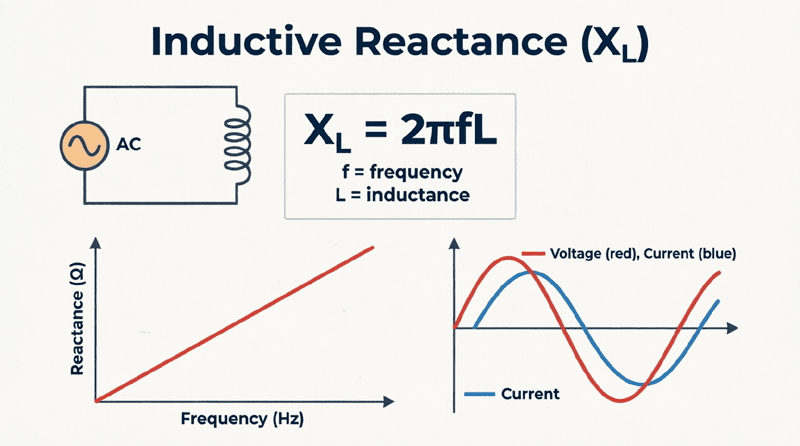
- At a specific frequency called the Self-Resonant Frequency (SRF), the inductive reactance and capacitive reactance cancel each other out, and the coil acts like a pure resistor.
- Above the SRF, the coil actually behaves like a capacitor, not an inductor!
This is why high-frequency inductors (like those used in RF circuits) are carefully designed with specific winding techniques (like “honeycomb” or “basket weave” windings) to minimize parasitic capacitance and push the SRF as high as possible.
The inductance of a coil is a fundamental electrical property dictated by its physical geometry and the materials used in its construction. By understanding the relationship between the number of turns, core permeability, cross-sectional area, and coil length, engineers can precisely design inductors for any application, from massive power grid transformers to microscopic RF filters on a smartphone motherboard.
Key takeaways from this guide include:
- Self-Inductance: A coil induces a voltage in itself when its current changes, opposing that change (Back EMF).
- The Unit: Inductance is measured in Henrys (H). One Henry induces one volt when the current changes at one ampere per second.
- The Formula: $L = \frac{N^2 \mu A}{l}$. Inductance scales with the square of the turns ($N^2$), making the number of windings the most powerful design variable.
- Induced EMF: Calculated by $e = -L \frac{di}{dt}$. The induced voltage depends on the rate of change of current, not the absolute amount of current.
- Real-World Imperfections: Physical coils have DC resistance (causing heat) and parasitic capacitance (limiting high-frequency use via the Self-Resonant Frequency).
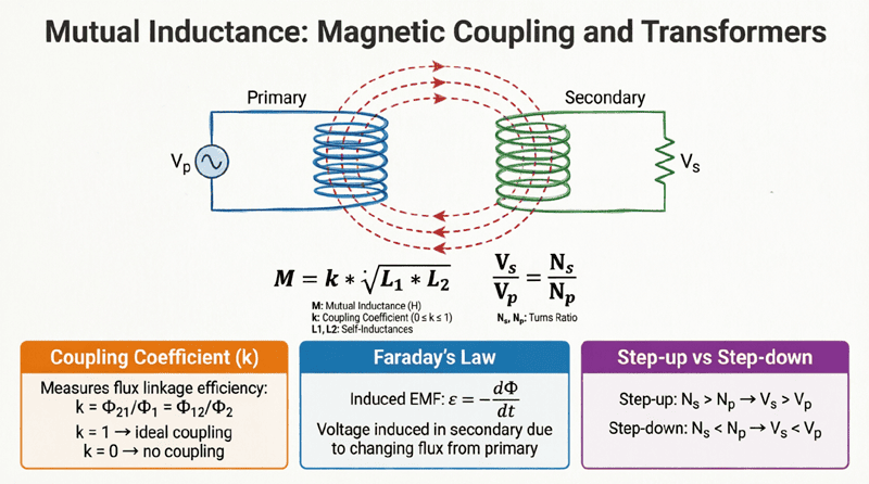
Mastering the inductance of a coil provides the necessary bridge between the physical construction of a component and its mathematical behavior in a circuit. In the next article, we will expand on this concept by exploring what happens when the magnetic field of one coil interacts with a second nearby coil, introducing the fascinating concept of Mutual Inductance.