Electronic System
Electronic System: Complete Guide to Control Systems Fundamentals
Introduction to Electronic System
In our modern world, electronic systems are everywhere—from the thermostat controlling your home’s temperature to the sophisticated autopilot systems guiding aircraft across oceans. These systems form the backbone of modern automation, enabling machines to perform tasks with precision, consistency, and intelligence that would be impossible through manual control alone.
An electronic system is an organized collection of components that work together to process input signals and produce desired output responses. Whether it’s a simple light dimmer switch or a complex industrial robot, every electronic system follows fundamental principles that govern how information flows, how decisions are made, and how actions are executed.
Understanding electronic systems is crucial for:
- Engineers: Designing efficient control systems for industrial applications
- Technicians: Troubleshooting and maintaining automated equipment
- Students: Building a foundation for advanced control theory
- Hobbyists: Creating smart home devices and robotics projects
This comprehensive guide will explore the fundamental concepts of electronic systems, their components, classifications, and real-world applications. We’ll examine how systems process information, make decisions, and interact with their environment to achieve specific objectives.
What is an Electronic System?
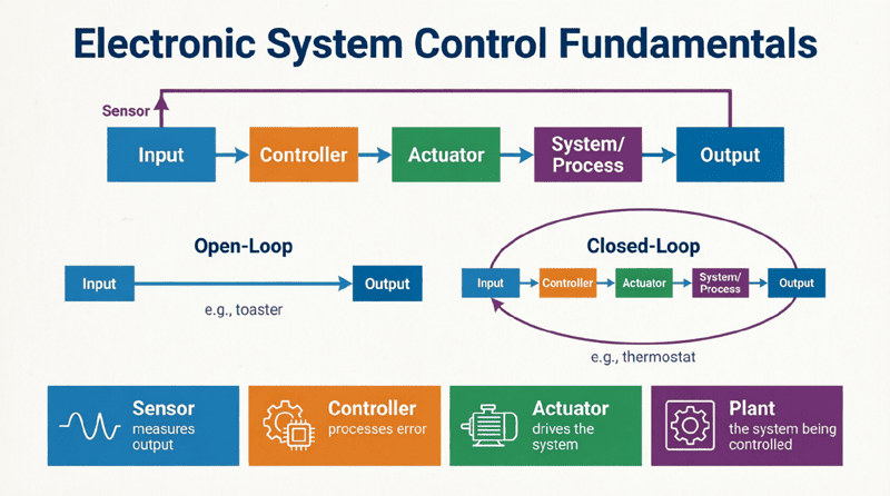
An electronic system is a collection of interconnected components that process input signals to produce desired outputs. It typically consists of sensors (inputs), processing units (controllers), and actuators (outputs) working together to achieve a specific function or control objective.
Fundamental Components of Electronic Systems
Every electronic system, regardless of complexity, consists of three fundamental components that work in harmony to achieve the system’s objectives.
1. Input Elements (Sensors)
Input elements are the system’s “senses”—they detect physical quantities from the environment and convert them into electrical signals that the system can process.
Common Types of Sensors:
Temperature Sensors:
- Thermocouples: Generate voltage proportional to temperature difference
- RTDs (Resistance Temperature Detectors): Change resistance with temperature
- Thermistors: Semiconductor devices with temperature-dependent resistance
- Example: A home thermostat uses temperature sensors to monitor room temperature
Position/Displacement Sensors:
- Potentiometers: Variable resistors that change with position
- LVDTs (Linear Variable Differential Transformers): Measure linear displacement
- Encoders: Convert angular or linear position to digital signals
- Example: Robotic arm joints use encoders to track position
Pressure Sensors:
- Strain gauges: Measure deformation under pressure
- Piezoelectric sensors: Generate voltage when pressure is applied
- Capacitive pressure sensors: Change capacitance with pressure
- Example: Automotive tire pressure monitoring systems
Flow Sensors:
- Turbine flow meters: Measure fluid flow rate
- Ultrasonic flow meters: Use sound waves to measure flow
- Differential pressure flow meters: Measure pressure drop across restriction
- Example: Water treatment plants monitor flow rates
Light Sensors:
- Photodiodes: Convert light to current
- Phototransistors: Light-sensitive transistors
- LDRs (Light Dependent Resistors): Change resistance with light intensity
- Example: Automatic street lighting systems
2. Processing Elements (Controllers)
The processing element is the “brain” of the system—it receives input signals, performs calculations or logical operations, and determines the appropriate output actions.
Types of Controllers:
Analog Controllers:
- Use operational amplifiers, resistors, and capacitors
- Process continuous signals
- Fast response, simple design
- Example: Analog PID controllers in industrial processes
Digital Controllers:
- Microcontrollers (Arduino, PIC, AVR)
- Microprocessors (ARM, x86)
- DSPs (Digital Signal Processors)
- FPGAs (Field-Programmable Gate Arrays)
- Example: Arduino-based home automation systems
Programmable Logic Controllers (PLCs):
- Ruggedized industrial computers
- Ladder logic programming
- Real-time control
- Example: Manufacturing assembly line control
Embedded Systems:
- Dedicated computer systems within larger systems
- Real-time operating systems (RTOS)
- Low power consumption
- Example: Automotive engine control units (ECUs)
Processing Functions:
- Signal Conditioning:
- Amplification: Increase signal strength
- Filtering: Remove unwanted noise
- Linearization: Convert nonlinear signals to linear
- Isolation: Protect system from high voltages
- Computation:
- Mathematical calculations
- Logical decisions (IF-THEN-ELSE)
- Comparison operations
- Data processing algorithms
- Control Algorithms:
- ON/OFF control (bang-bang control)
- Proportional-Integral-Derivative (PID) control
- Fuzzy logic control
- Adaptive control
- Model predictive control
3. Output Elements (Actuators)
Output elements are the system’s “muscles”—they convert electrical signals from the controller into physical actions that affect the environment or the controlled process.
Types of Actuators:
Electric Actuators:
- Motors:
- DC motors: Variable speed, easy control
- AC motors: High power, industrial applications
- Stepper motors: Precise position control
- Servo motors: Closed-loop position/speed control
- Example: Robotic arm movement
- Solenoids:
- Electromagnetic coils that create linear motion
- Fast response, simple design
- Example: Door locks, valve control
- Relays:
- Electrically operated switches
- Isolate control circuit from load circuit
- Example: Motor starters, lighting control
Pneumatic Actuators:
- Use compressed air to create motion
- Clean, fast, safe in explosive environments
- Example: Factory automation, packaging machines
Hydraulic Actuators:
- Use pressurized fluid (oil) to create motion
- High force capability
- Example: Heavy machinery, aircraft control surfaces
Thermal Actuators:
- Heating elements
- Coolers (Peltier devices)
- Example: Temperature control systems
Display/Indication Devices:
- LEDs (Light Emitting Diodes)
- LCD displays
- Seven-segment displays
- Buzzers and speakers
- Example: System status indicators
What are the three main components of an electronic system?
The three main components are: 1) Input elements (sensors) that detect physical quantities, 2) Processing elements (controllers) that make decisions, and 3) Output elements (actuators) that perform physical actions.
System Block Diagrams
Block diagrams are essential tools for visualizing and understanding electronic systems. They provide a high-level view of how components interact without getting bogged down in circuit details.
Standard Block Diagram Elements
Blocks:
- Represent system components or functions
- Rectangular boxes with descriptive labels
- Example: “Temperature Sensor,” “PID Controller,” “Motor Driver”
Signals:
- Arrows showing signal flow direction
- Labeled with signal names or variables
- Can be analog or digital
Summing Points:
- Circles with + or – signs
- Combine multiple signals
- Used in feedback systems
Take-off Points:
- Branch points where signals split
- Same signal goes to multiple destinations
Creating Effective Block Diagrams
Step-by-Step Process:
- Identify System Objective:
- What is the system supposed to do?
- Example: “Maintain room temperature at 22°C”
- List Inputs and Outputs:
- Inputs: What does the system measure?
- Outputs: What does the system control?
- Example: Input = Temperature, Output = Heater power
- Identify Components:
- Sensors needed
- Processing requirements
- Actuators required
- Draw Signal Flow:
- Show how information moves through the system
- Indicate feedback paths if present
- Label Everything:
- Clear, descriptive names
- Signal variables (T, V, I, etc.)
- Units where appropriate
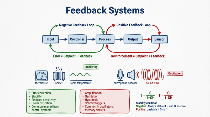
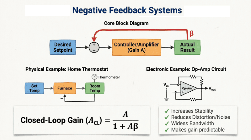
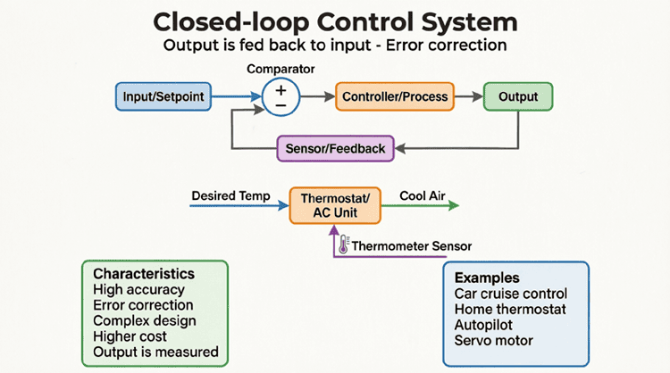
Example: Temperature Control System Block
[Desired Temp] → [Comparator] → [Controller] → [Heater] → [Room]
                    ↑                                |
                    |                                ↓
                    └──────[Temperature Sensor]←────┘
Signal Flow Explanation:
- Desired temperature is set by user
- Comparator calculates error (difference between desired and actual)
- Controller determines heater power based on error
- Heater warms the room
- Temperature sensor measures actual room temperature
- Feedback loop closes, allowing continuous adjustment
Classification of Electronic Systems
Electronic systems can be classified in several ways based on their characteristics and behavior.
1. Based on Signal Type
Analog Systems:
- Process continuous signals
- Infinite resolution within range
- Susceptible to noise
- Example: Analog audio amplifier
Digital Systems:
- Process discrete signals (0s and 1s)
- Finite resolution (depends on bit depth)
- Noise-immune
- Example: Digital thermometer
Mixed-Signal Systems:
- Combine analog and digital processing
- Use ADCs (Analog-to-Digital Converters) and DACs (Digital-to-Analog Converters)
- Most modern systems
- Example: Smartphone (analog sensors, digital processor)
2. Based on Time Behavior
Continuous-Time Systems:
- Signals exist at all times
- Described by differential equations
- Example: RC filter circuit
Discrete-Time Systems:
- Signals exist only at specific time intervals
- Described by difference equations
- Example: Digital audio processing
3. Based on Linearity
Linear Systems:
- Obey superposition principle
- Output proportional to input
- Easy to analyze mathematically
- Example: Resistor (V = IR)
Nonlinear Systems:
- Do not obey superposition
- Output not proportional to input
- More complex behavior
- Example: Diode (exponential I-V relationship)
4. Based on Time-Invariance
Time-Invariant Systems:
- Characteristics don’t change with time
- Same input always produces same output
- Example: Fixed resistor
Time-Variant Systems:
- Characteristics change with time
- Response depends on when input is applied
- Example: Aging battery
5. Based on Causality
Causal Systems:
- Output depends only on present and past inputs
- Physically realizable
- Example: All real-time control systems
Non-Causal Systems:
- Output depends on future inputs
- Not physically realizable in real-time
- Example: Post-processing of recorded data
System Characteristics and Performance Metrics
Understanding how to evaluate system performance is crucial for design and analysis.
Key Performance Metrics
1. Accuracy:
- How close the output is to the desired value
- Measured as error: Error = Desired – Actual
- Example: Temperature control accuracy ±0.5°C
2. Precision:
- Repeatability of measurements
- Consistency of output
- Example: Scale that gives same reading every time
3. Resolution:
- Smallest detectable change
- Depends on sensor and ADC bit depth
- Example: 12-bit ADC has 4096 levels
4. Sensitivity:
- Change in output per unit change in input
- High sensitivity = large output for small input
- Example: Microphone sensitivity in mV/Pa
5. Response Time:
- Time to reach desired output after input change
- Critical for real-time systems
- Example: Airbag deployment < 50ms
6. Bandwidth:
- Range of frequencies system can handle
- Higher bandwidth = faster response
- Example: Audio amplifier 20Hz-20kHz
7. Stability:
- System returns to equilibrium after disturbance
- Unstable systems oscillate or diverge
- Critical for safety
8. Reliability:
- Probability of failure-free operation
- Mean Time Between Failures (MTBF)
- Example: Industrial PLC MTBF > 100,000 hours
Practical Examples of Electronic Systems
Example 1: Automatic Street Lighting System
Objective: Turn lights ON at dusk and OFF at dawn automatically
Components:
- Input: LDR (Light Dependent Resistor) detects ambient light
- Processing: Comparator circuit or microcontroller
- Output: Relay switches street light ON/OFF
Operation:
- LDR resistance changes with light level
- Circuit compares light level to threshold
- When dark, relay energizes, turning light ON
- When light, relay de-energizes, turning light OFF
[Ambient Light] → [LDR Sensor] → [Comparator] → [Relay] → [Street Light]Example 2: Cruise Control System
Objective: Maintain constant vehicle speed despite hills and wind
Components:
- Input: Speed sensor (measures actual speed)
- Processing: PID controller (compares to set speed)
- Output: Throttle actuator (adjusts engine power)
Operation:
- Driver sets desired speed (e.g., 65 mph)
- Speed sensor measures actual speed
- Controller calculates speed error
- Adjusts throttle to minimize error
- Continuous feedback maintains speed
[Set Speed] → [Comparator] → [PID Controller] → [Throttle] → [Vehicle]
                 ↑                                    |
                 |                                    ↓
                 └──────[Speed Sensor]←───────────────┘
Example 3: Washing Machine Control System
Objective: Automate washing cycle with water level, temperature, and timing control
Components:
- Inputs:
- Water level sensor
- Temperature sensor
- Door switch
- Cycle selector
- Processing: Microcontroller with programmed cycles
- Outputs:
- Water inlet valve
- Heater
- Motor (agitate/spin)
- Drain pump
- Display
Operation:
- User selects cycle and options
- System fills water to correct level
- Heats water to selected temperature
- Agitates clothes for programmed time
- Drains water, spins to extract water
- Signals completion
System Design Considerations
When designing electronic systems, several factors must be carefully considered:
1. Requirements Analysis
- Clearly define what the system must do
- Identify constraints (cost, size, power)
- Determine performance specifications
- Consider environmental conditions
2. Component Selection
- Choose sensors with appropriate range and accuracy
- Select controller with sufficient processing power
- Size actuators for required force/speed
- Consider availability and cost
3. Power Supply Design
- Determine voltage and current requirements
- Choose between AC/DC, battery, or mains power
- Include regulation and protection
- Consider efficiency and heat dissipation
4. Signal Integrity
- Minimize noise and interference
- Use proper grounding and shielding
- Implement filtering where needed
- Consider signal conditioning
5. Safety and Protection
- Overcurrent protection
- Overvoltage protection
- Thermal protection
- Fail-safe design
- Emergency stop functionality
6. Maintainability
- Easy access to components
- Clear documentation
- Modular design
- Diagnostic capabilities
- Standard parts
7. Cost Optimization
- Balance performance vs. cost
- Consider total cost of ownership
- Minimize component count
- Use standard components
- Design for manufacturability
Modern Trends in Electronic Systems
1. Internet of Things (IoT)
- Systems connected to internet
- Remote monitoring and control
- Cloud-based data processing
- Example: Smart home systems
2. Artificial Intelligence Integration
- Machine learning algorithms
- Predictive maintenance
- Adaptive control
- Example: AI-powered HVAC systems
3. Wireless Communication
- Bluetooth, WiFi, Zigbee
- Reduced wiring complexity
- Mobile app control
- Example: Wireless sensor networks
4. Energy Efficiency
- Low-power components
- Sleep modes and power management
- Energy harvesting
- Example: Battery-powered IoT devices
5. Miniaturization
- Surface-mount components
- System-on-Chip (SoC)
- Wearable electronics
- Example: Smartwatches
Electronic systems form the foundation of modern automation and control. By understanding the fundamental components—sensors, controllers, and actuators—and how they interact through well-defined signal flows, engineers can design systems that perform complex tasks with precision and reliability.
Key takeaways from this guide include:
- Three Core Components: Every electronic system consists of input elements (sensors), processing elements (controllers), and output elements (actuators) working together.
- Block Diagrams: Visual representation using block diagrams is essential for understanding, designing, and communicating system architecture.
- Classification: Systems can be classified by signal type (analog/digital), time behavior (continuous/discrete), linearity, and other characteristics.
- Performance Metrics: Accuracy, precision, response time, stability, and reliability are critical parameters for evaluating system performance.
- Design Considerations: Successful system design requires careful attention to requirements, component selection, power management, safety, and cost.
- Real-World Applications: From simple automatic lighting to complex cruise control systems, electronic systems are ubiquitous in modern life.
- Future Trends: IoT, AI integration, wireless communication, and energy efficiency are shaping the future of electronic systems.
As technology continues to advance, electronic systems will become increasingly sophisticated, intelligent, and interconnected. Mastering these fundamentals provides the foundation for tackling more advanced topics in control theory, automation, and system design.
Whether you’re designing a simple temperature controller or a complex industrial automation system, the principles outlined in this guide will serve as your roadmap to success. The key is to start with clear requirements, choose appropriate components, design robust control algorithms, and always prioritize safety and reliability.