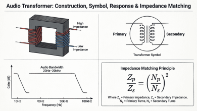
Transformer Basics and Transformer Principles
Complete Guide to How Transformers Work
Transformers are one of the most essential and ubiquitous devices in electrical engineering and power systems. From the massive units stepping up voltage at power plants to the small adapters charging your smartphone, transformers play a critical role in efficiently transmitting and utilizing electrical energy.
At its core, a transformer is a static electrical device that transfers electrical energy between two or more circuits through electromagnetic induction. Transformers can increase (step up) or decrease (step down) AC voltage levels while maintaining the same frequency, making them indispensable for power distribution, electrical isolation, impedance matching, and countless other applications.
Understanding transformer basics is fundamental for anyone working with electrical systems, whether you’re an electrical engineer, technician, student, or hobbyist. This comprehensive guide will explore the fundamental principles of transformer operation, key parameters, types, and practical applications.
What is a Transformer?
A transformer is a static electrical device that transfers energy between circuits through electromagnetic induction. It consists of two or more coils (windings) linked by a magnetic core. Transformers can step up or step down AC voltage levels while maintaining power (minus losses) and are essential for efficient power transmission and distribution.
The Fundamental Principle of Transformer Operation
Electromagnetic Induction
Transformers operate on the principle of electromagnetic induction, discovered by Michael Faraday in 1831. Faraday’s Law states that a changing magnetic field through a coil of wire induces a voltage across the coil.
Faraday’s Law:
$e = -N \frac{d\Phi}{dt}$
Where:
- e = Induced electromotive force (EMF) in volts
- N = Number of turns in the coil
- dΦ/dt = Rate of change of magnetic flux in webers per second
The negative sign indicates Lenz’s Law: the induced EMF opposes the change in magnetic flux that created it.
How a Transformer Works
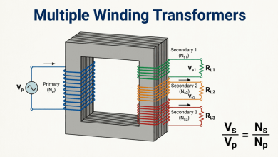
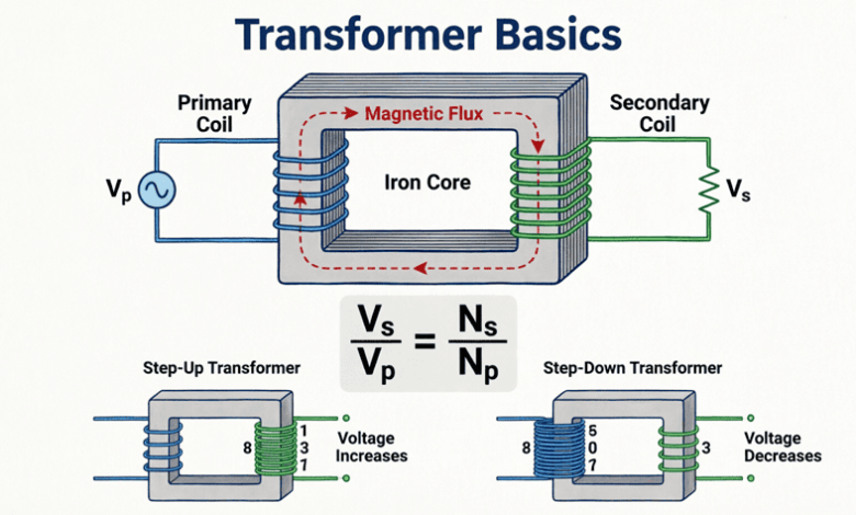
A basic transformer consists of two coils (windings) wound on a common magnetic core:
- Primary Winding: Connected to the AC power source
- Secondary Winding: Connected to the load
- Magnetic Core: Provides a low-reluctance path for magnetic flux
Step-by-Step Operation:
Step 1: An alternating voltage is applied to the primary winding, causing an alternating current to flow.
Step 2: This alternating current creates a continuously changing magnetic flux in the core.
Step 3: The changing magnetic flux links with both the primary and secondary windings.
Step 4: According to Faraday’s Law, the changing flux induces voltages in both windings.
Step 5: The induced voltage in the secondary winding supplies power to the connected load.
Key Point: There is no electrical connection between the primary and secondary windings—energy is transferred entirely through the magnetic field. This provides electrical isolation between input and output circuits.
How does a transformer transfer energy?
A transformer transfers energy through electromagnetic induction. AC current in the primary winding creates a changing magnetic flux in the core, which induces a voltage in the secondary winding. There is no direct electrical connection between windings—energy transfers entirely through the magnetic field.
Transformer Construction Elements
Core Materials
The transformer core provides a path for magnetic flux and significantly affects efficiency. Common core materials include:
1. Silicon Steel (Most Common):
- Laminated sheets to reduce eddy current losses
- Contains 3-5% silicon to increase resistivity
- Used in power and distribution transformers
- Operating frequency: 50-60 Hz
2. Ferrite:
- Ceramic magnetic material
- High resistivity (low eddy current losses)
- Used in high-frequency transformers (kHz to MHz)
- Common in switch-mode power supplies
3. Amorphous Steel:
- Non-crystalline structure
- Very low core losses (70-80% less than silicon steel)
- Expensive but highly efficient
- Used in high-efficiency distribution transformers
4. Air Core:
- No magnetic material
- Used in very high-frequency applications (RF)
- Low inductance, no core losses
- Common in radio frequency transformers
Windings
Transformer windings are typically made of copper or aluminum conductors:
Copper Windings:
- Higher conductivity
- Smaller size for same power rating
- More expensive
- Better mechanical strength
Aluminum Windings:
- Lower cost
- Lighter weight
- Larger size required
- Common in distribution transformers
Winding Arrangements:
- Concentric: One winding inside the other (most common)
- Sandwich/Interleaved: Windings alternate in sections (reduces leakage reactance)
Insulation
Proper insulation is critical for transformer safety and longevity:
Types of Insulation:
- Turn insulation: Between individual wire turns
- Layer insulation: Between winding layers
- Winding insulation: Between primary and secondary
- Core insulation: Between core laminations
Insulation Materials:
- Paper, pressboard, enamel (small transformers)
- Oil-impregnated paper (power transformers)
- Epoxy resin (dry-type transformers)
- Silicone rubber (high-temperature applications)
The Turns Ratio and Voltage Transformation
Turns Ratio Definition
The turns ratio (also called transformation ratio) is the ratio of the number of turns in the primary winding to the number of turns in the secondary winding:
$a = \frac{N_p}{N_s}$
Where:
- a = Turns ratio
- N_p = Number of turns in primary winding
- N_s = Number of turns in secondary winding
Voltage Relationship
For an ideal transformer (no losses), the voltage ratio equals the turns ratio:
$\frac{V_p}{V_s} = \frac{N_p}{N_s} = a$
Or rearranged:
$V_s = V_p \times \frac{N_s}{N_p}$
Where:
- V_p = Primary voltage
- V_s = Secondary voltage
Step-Up vs. Step-Down Transformers
Step-Down Transformer:
- N_p > N_s (more primary turns)
- V_s < V_p (output voltage lower than input)
- a > 1
- Example: 120V to 12V adapter (a = 10)
Step-Up Transformer:
- N_p < N_s (fewer primary turns)
- V_s > V_p (output voltage higher than input)
- a < 1
- Example: Power plant generator step-up (13.8kV to 230kV)
Isolation Transformer:
- N_p = N_s (equal turns)
- V_s = V_p (same voltage)
- a = 1
- Provides electrical isolation without voltage change
Current Relationship
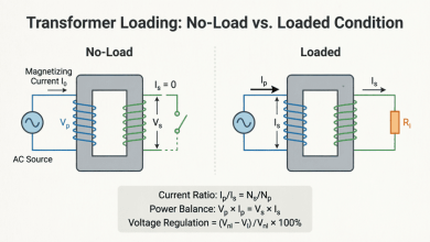
Since power is conserved in an ideal transformer (P_in = P_out):
$V_p \times I_p = V_s \times I_s$
Therefore:
$\frac{I_p}{I_s} = \frac{N_s}{N_p} = \frac{1}{a}$
Or:
$I_s = I_p \times \frac{N_p}{N_s} = I_p \times a$
Key Insight: The current ratio is inverse to the turns ratio. A step-down transformer (voltage decreases) will have increased current, and vice versa.
What is the turns ratio of a transformer?
The turns ratio is the ratio of primary turns to secondary turns (a = N_p/N_s). It determines the voltage transformation: V_s = V_p × (N_s/N_p). For example, a transformer with 1000 primary turns and 100 secondary turns has a turns ratio of 10:1 and will step down voltage by a factor of 10.
Ideal vs. Real Transformers
Ideal Transformer Assumptions
An ideal transformer is a theoretical model with the following assumptions:
- No Winding Resistance: Zero copper losses (I²R = 0)
- No Core Losses: Zero hysteresis and eddy current losses
- No Leakage Flux: All flux links both windings perfectly
- Infinite Core Permeability: Zero magnetizing current required
- 100% Efficiency: All input power transfers to output
Ideal Transformer Equations:
- $\frac{V_p}{V_s} = \frac{N_p}{N_s}$
- $\frac{I_p}{I_s} = \frac{N_s}{N_p}$
- $P_{in} = P_{out}$ (100% efficiency)
- $S_{in} = S_{out}$ (apparent power conserved)
Real Transformer Characteristics
Real transformers deviate from the ideal model due to:
1. Winding Resistance:
- Copper wire has finite resistance
- Causes I²R power losses (heat)
- Results in voltage drop under load
2. Core Losses:
- Hysteresis Loss: Energy lost reversing magnetic domains
- Eddy Current Loss: Circulating currents in core material
- Present even with no load (no-load losses)
3. Leakage Flux:
- Not all flux links both windings
- Causes leakage reactance
- Results in voltage regulation issues
4. Magnetizing Current:
- Finite core permeability requires current to establish flux
- Typically 2-5% of full-load current
- Lags voltage by nearly 90°
5. Efficiency:
- Real transformers: 95-99% efficient
- Large power transformers: 98-99.5%
- Small transformers: 85-95%
Equivalent Circuit
A real transformer can be modeled using an equivalent circuit that includes:
- R_p, R_s: Primary and secondary winding resistances
- X_p, X_s: Primary and secondary leakage reactances
- R_c: Core loss resistance (accounts for hysteresis and eddy currents)
- X_m: Magnetizing reactance
This model allows accurate calculation of:
- Voltage regulation
- Efficiency
- Performance under various load conditions
Transformer Power and Efficiency
Power Relationships
Apparent Power (S):
$S = V \times I$ (measured in VA or kVA)
For an ideal transformer:
$S_p = S_s$
$V_p \times I_p = V_s \times I_s$
Real Power (P):
$P = V \times I \times \cos\phi$ (measured in W or kW)
Where $\cos\phi$ is the power factor of the load.
Reactive Power (Q):
$Q = V \times I \times \sin\phi$ (measured in VAR or kVAR)
Transformer Efficiency
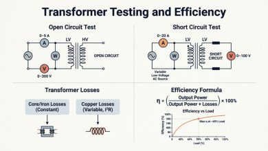
Efficiency is the ratio of output power to input power:
$\eta = \frac{P_{out}}{P_{in}} \times 100\%$
Or:
$\eta = \frac{P_{out}}{P_{out} + P_{losses}} \times 100\%$
Transformer Losses:
- Copper Losses (Variable):
- $P_{copper} = I_p^2 R_p + I_s^2 R_s$
- Varies with load current squared
- Also called I²R losses
- Core/Iron Losses (Constant):
- $P_{core} = P_{hysteresis} + P_{eddy}$
- Constant regardless of load
- Present whenever transformer is energized
Maximum Efficiency Condition:
Maximum efficiency occurs when:
Copper losses = Core losses
This typically happens at 50-75% of full load for distribution transformers.
All-Day Efficiency
For transformers that operate continuously with varying loads (like distribution transformers), all-day efficiency is more meaningful:
$\eta_{all-day} = \frac{\text{Energy output in 24 hours}}{\text{Energy input in 24 hours}} \times 100\%$
This accounts for core losses that occur 24/7, even when the transformer supplies no load.
Practical Examples and Calculations
Example 1: Calculating Secondary Voltage
Problem: A transformer has 800 turns on the primary and 200 turns on the secondary. If the primary voltage is 240V, calculate the secondary voltage.
Solution:
Given:
- N_p = 800 turns
- N_s = 200 turns
- V_p = 240V
Calculate turns ratio:
$a = \frac{N_p}{N_s} = \frac{800}{200} = 4$
Calculate secondary voltage:
$V_s = V_p \times \frac{N_s}{N_p} = 240 \times \frac{200}{800}$
$V_s = 240 \times 0.25 = 60V$
Result: This is a step-down transformer with 60V secondary output.
Example 2: Calculating Current
Problem: A 240V/120V step-down transformer supplies a load drawing 10A at 120V. Calculate the primary current (assume ideal transformer).
Solution:
Given:
- V_p = 240V
- V_s = 120V
- I_s = 10A
Using power conservation:
$V_p \times I_p = V_s \times I_s$
$I_p = \frac{V_s \times I_s}{V_p} = \frac{120 \times 10}{240}$
$I_p = \frac{1200}{240} = 5A$
Alternative method using turns ratio:
$a = \frac{V_p}{V_s} = \frac{240}{120} = 2$
$I_p = \frac{I_s}{a} = \frac{10}{2} = 5A$
Result: Primary current is 5A.
Example 3: Transformer Efficiency
Problem: A 10 kVA transformer has core losses of 150W and full-load copper losses of 250W. Calculate the efficiency at full load with a power factor of 0.8.
Solution:
Given:
- Rating = 10 kVA
- Core losses = 150W
- Copper losses (full load) = 250W
- Power factor = 0.8
Calculate output power:
$P_{out} = \text{kVA} \times \text{PF} = 10,000 \times 0.8 = 8,000W$
Calculate total losses:
$P_{losses} = P_{core} + P_{copper} = 150 + 250 = 400W$
Calculate input power:
$P_{in} = P_{out} + P_{losses} = 8,000 + 400 = 8,400W$
Calculate efficiency:
$\eta = \frac{P_{out}}{P_{in}} \times 100\% = \frac{8,000}{8,400} \times 100\%$
$\eta = 95.24\%$
Result: The transformer efficiency at full load is 95.24%.
Applications of Transformers
Transformers are used in countless applications across electrical and electronic systems:
1. Power Transmission and Distribution
- Step-up transformers: Increase voltage at power plants (13.8kV to 230-765kV) for efficient long-distance transmission
- Step-down transformers: Reduce voltage for distribution (230kV to 13.8kV) and final utilization (13.8kV to 120/240V)
2. Electrical Isolation
- Isolation transformers: Provide safety by isolating circuits while maintaining voltage
- Medical equipment: Protect patients from electrical shock
- Laboratory equipment: Prevent ground loops and noise
3. Impedance Matching
- Audio systems: Match speaker impedance to amplifier output
- RF circuits: Match antenna impedance to transmitter
- Maximum power transfer: Optimize power delivery
4. Voltage Conversion
- Power adapters: Convert 120/240V AC to low voltage DC (phone chargers, laptop adapters)
- Industrial equipment: Provide required voltage levels for machinery
- HVAC systems: Control voltage for thermostats and controls
5. Measurement and Protection
- Current transformers (CT): Step down high currents for measurement
- Potential transformers (PT): Step down high voltages for metering
- Protective relaying: Isolate measurement circuits from high voltage
6. Signal Processing
- Audio transformers: Couple audio signals between stages
- Pulse transformers: Transfer digital pulses with isolation
- RF transformers: Impedance matching in radio circuits
Transformers are fundamental devices in electrical engineering that enable efficient power transmission, voltage conversion, and electrical isolation. Understanding transformer basics is essential for anyone working with electrical systems.
Key takeaways from this guide:
- Operating Principle: Transformers work on electromagnetic induction—changing magnetic flux induces voltage in coupled windings with no direct electrical connection.
- Turns Ratio: The ratio of primary to secondary turns determines voltage transformation: $V_s = V_p \times (N_s/N_p)$
- Current Relationship: Current transforms inversely to voltage: $I_s = I_p \times (N_p/N_s)$
- Power Conservation: In ideal transformers, input power equals output power (minus losses in real transformers).
- Types:
- Step-down: Reduces voltage (N_p > N_s)
- Step-up: Increases voltage (N_p < N_s)
- Isolation: Same voltage, provides isolation (N_p = N_s)
- Losses and Efficiency: Real transformers have copper losses (I²R) and core losses (hysteresis + eddy currents), resulting in 95-99% efficiency.
- Applications: From power grid transmission to smartphone chargers, transformers are ubiquitous in modern electrical systems.
Mastering these fundamentals provides the foundation for understanding more advanced transformer topics including construction details, loading characteristics, three-phase configurations, and specialized transformer types covered in subsequent tutorial guides.