4017 Johnson Counter
4017 Johnson Counter: Complete Guide to Decade Counter IC Design
Introduction to the 4017 Johnson Counter
The 4017 Johnson Counter (also known as CD4017 or 74HC4017) is one of the most versatile and popular integrated circuits in digital electronics. This CMOS decade counter features 10 decoded outputs that activate sequentially with each clock pulse, making it ideal for LED chasers, sequential control systems, frequency division, and timing applications.
Unlike standard binary counters that require external decoding logic, the 4017 has built-in decoding, providing direct access to each of the 10 states (Q0-Q9). This “one-hot” output configuration simplifies circuit design and eliminates the need for additional decoder ICs.
The 4017 Johnson counter is widely used in:
- LED Chaser Circuits: Creating running light displays
- Sequential Controllers: Automating multi-step processes
- Frequency Dividers: Dividing clock frequency by 2-10
- Timers and Sequencers: Generating timed output sequences
- Game Electronics: Random selection and sequencing
- Educational Projects: Teaching digital logic concepts
This comprehensive guide will explore the architecture, pin configuration, operating principles, and practical applications of the 4017 Johnson counter. We will examine how to cascade multiple 4017 ICs for extended counting sequences, design LED chaser circuits, and implement various timing and control applications.
What is a 4017 Johnson Counter?
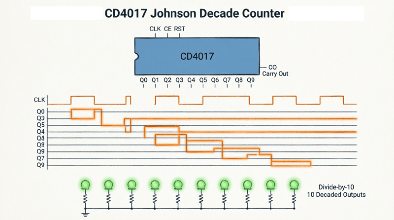
The 4017 is a CMOS decade counter with 10 decoded outputs (Q0-Q9). With each clock pulse, exactly one output goes HIGH while all others remain LOW, cycling through Q0→Q1→…→Q9→Q0. It’s called a Johnson counter because of its internal shift register architecture. The IC includes reset, clock enable, and carry-out pins for cascading.
Understanding Johnson Counters
What is a Johnson Counter?
A Johnson counter (also called a twisted ring counter or switch-tail ring counter) is a type of shift register-based counter where the inverted output of the last flip-flop is fed back to the input of the first flip-flop. This creates a specific counting sequence that differs from standard binary or ring counters.
Johnson Counter Characteristics:
- MOD value: 2n (where n is the number of flip-flops)
- States: For 5 flip-flops: MOD-10 (10 states)
- Output pattern: Only one output HIGH at a time (one-hot)
- Sequence: Q0→Q1→Q2→…→Qn-1→Q0
Comparison with Other Counters:
| Counter Type | Flip-Flops | MOD | Outputs Active | Decoding Required |
|---|---|---|---|---|
| Binary | 4 | 16 | Multiple | Yes |
| Ring | 10 | 10 | One | No |
| Johnson | 5 | 10 | One | No |
| 4017 (Johnson) | 5 | 10 | One | Built-in |
The 4017 uses a 5-stage Johnson counter internally, providing 10 decoded outputs without external logic.
Advantages of Johnson Counters
1. Self-Decoding:
Each state has a unique output, eliminating the need for external decoding logic.
2. Glitch-Free:
Only one output changes at a time, preventing decoding glitches common in binary counters.
3. Simple Design:
Fewer components required compared to binary counter + decoder combinations.
4. Predictable Timing:
All outputs have identical propagation delays.
5. Easy Cascading:
Carry-out pin simplifies connecting multiple counters.
Why is the 4017 called a Johnson counter?
The 4017 uses a 5-stage Johnson counter (twisted ring counter) architecture internally. The inverted output of the last flip-flop feeds back to the first flip-flop input, creating a 10-state sequence. This design provides 10 decoded outputs without external logic, making it more efficient than binary counters.
4017 Pin Configuration and Functions
16-Pin DIP Package
The 4017 comes in a standard 16-pin DIP (Dual Inline Package) or SOIC surface-mount package.
Pin Assignments:
| Pin | Name | Function | I/O |
|---|---|---|---|
| 1 | Q5 | Output 5 | Output |
| 2 | Q1 | Output 1 | Output |
| 3 | Q0 | Output 0 | Output |
| 4 | Q2 | Output 2 | Output |
| 5 | Q6 | Output 6 | Output |
| 6 | Q7 | Output 7 | Output |
| 7 | Q3 | Output 3 | Output |
| 8 | VSS | Ground (0V) | Power |
| 9 | Q8 | Output 8 | Output |
| 10 | Q4 | Output 4 | Output |
| 11 | Q9 | Output 9 | Output |
| 12 | CO | Carry Out | Output |
| 13 | CLK | Clock Input | Input |
| 14 | EN | Clock Enable | Input |
| 15 | RST | Reset | Input |
| 16 | VDD | Supply Voltage (+3V to +15V) | Power |
Detailed Pin Functions
Outputs (Q0-Q9):
- Pins 3, 2, 4, 7, 10, 1, 5, 6, 9, 11
- Only ONE output is HIGH at any time
- Sequence: Q0→Q1→Q2→Q3→Q4→Q5→Q6→Q7→Q8→Q9→Q0
- Can source/sink up to 10mA (depending on supply voltage)
Clock Input (CLK – Pin 13):
- Positive edge-triggered
- Advances counter on rising edge (LOW→HIGH transition)
- Must be clean digital signal
- Maximum frequency: 5 MHz (typical at 10V)
Clock Enable (EN – Pin 14):
- Active LOW
- When EN = LOW: Counter advances on clock pulses
- When EN = HIGH: Counter is disabled (holds current state)
- Useful for gating clock or synchronizing multiple counters
Reset (RST – Pin 15):
- Active HIGH
- When RST = HIGH: Counter resets to Q0 (all outputs LOW except Q0)
- When RST = LOW: Normal counting operation
- Asynchronous (immediate reset, doesn’t wait for clock)
Carry Out (CO – Pin 12):
- Goes HIGH when count reaches Q9 (state 9)
- Returns LOW when counter resets to Q0
- Used for cascading multiple 4017 ICs
- Frequency = Input clock / 10
Power Supply:
- VDD (Pin 16): +3V to +15V (CMOS)
- VSS (Pin 8): Ground (0V)
- Typical: +5V or +9V
Truth Table
| RST | EN | CLK | Operation |
|---|---|---|---|
| H | X | X | Reset to Q0 |
| L | H | X | No change (hold) |
| L | L | ↑ | Count advance |
| L | L | L | No change |
| L | L | H | No change |
H = HIGH, L = LOW, X = Don’t care, ↑ = Rising edge
Basic Operating Principles
Counting Sequence
The 4017 cycles through 10 states with each clock pulse:
State Progression:
| Clock Pulse | Active Output | Binary Equivalent |
|---|---|---|
| 0 (Reset) | Q0 | 0000 |
| 1 | Q1 | 0001 |
| 2 | Q2 | 0010 |
| 3 | Q3 | 0011 |
| 4 | Q4 | 0100 |
| 5 | Q5 | 0101 |
| 6 | Q6 | 0110 |
| 7 | Q7 | 0111 |
| 8 | Q8 | 1000 |
| 9 | Q9 | 1001 |
| 10 | Q0 | 0000 (repeat) |
Timing Diagram
Clock to Output Relationship:
- On each rising edge of CLK, the HIGH output shifts to the next pin
- Q0→Q1→Q2→…→Q9→Q0
- Only one output HIGH at any time
- Carry-out (CO) goes HIGH when Q9 is active
Reset Operation:
- When RST goes HIGH, counter immediately resets to Q0
- All other outputs go LOW
- Reset is asynchronous (doesn’t wait for clock)
Clock Enable:
- When EN is HIGH, clock pulses are ignored
- Counter holds current state
- When EN goes LOW, counting resumes
Frequency Division
The 4017 acts as a divide-by-N counter:
Division Ratios:
- Q0 output: Input frequency (no division)
- Q1 output: ÷10 (full cycle)
- CO output: 10 (square wave, 50% duty cycle)
Custom Division:
By using the reset pin, you can create custom division ratios:
- Reset at Q2: 3 counter
- Reset at Q4: 5 counter
- Reset at Q6: ÷7 counter
Example: Divide-by-6
- Connect Q6 to RST pin
- Counter cycles: Q0→Q1→Q2→Q3→Q4→Q5→Q0
- Division ratio: 6
- Output frequency: $f_{out} = f_{in} / 6$
Practical Circuit Designs
Example 1: Basic LED Chaser Circuit
The classic 4017 application is an LED chaser (running light) where LEDs illuminate sequentially.
Components Required:
- 4017 IC (CD4017 or 74HC4017)
- 10 × LEDs (any color)
- 10 × 330Ω resistors (current limiting)
- 555 timer IC (clock generator)
- 9V battery
- Breadboard and wires
Circuit Connections:
4017 Connections:
- Pin 16 (VDD) → +9V
- Pin 8 (VSS) → GND
- Pin 15 (RST) → GND (normal operation)
- Pin 14 (EN) → GND (enable counting)
- Pin 13 (CLK) → 555 timer output
- Pins 3, 2, 4, 7, 10, 1, 5, 6, 9, 11 (Q0-Q9) → LEDs through 330Ω resistors
555 Timer (Astable Mode):
- Configured to generate 1-10 Hz clock
- Output (Pin 3) → 4017 CLK (Pin 13)
- Adjust frequency with potentiometer for variable speed
LED Connections:
- LED anode → 4017 output through 330Ω resistor
- LED cathode → GND
- Each LED connects to one output (Q0-Q9)
Operation:
- Power on: Q0 goes HIGH, LED 0 illuminates
- Clock pulse: Q0→LOW, Q1→HIGH, LED 1 illuminates
- Continue: LEDs light sequentially Q0→Q1→…→Q9→Q0
- Speed determined by 555 timer frequency
Current Calculation:
$$I_{LED} = \frac{9V – 2V}{330\Omega} = \frac{7V}{330\Omega} = 21mA$$
Use 470Ω resistors for 15mA or 680Ω for 10mA.
Example 2: Variable MOD Counter
Create a counter with custom modulus by using the reset pin.
MOD-5 Counter:
- Connect Q5 (Pin 1) to RST (Pin 15)
- Counter cycles: Q0→Q1→Q2→Q3→Q4→Q0
- Division ratio: ÷5
- Useful for specific timing applications
MOD-3 Counter:
- Connect Q3 (Pin 7) to RST (Pin 15)
- Counter cycles: Q0→Q1→Q2→Q0
- Division ratio: ÷3
Circuit:
- 4017 IC
- Wire from Qn to RST (where n = desired MOD)
- Clock input
- Outputs Q0 to Q(n-1) available
Note: The reset is asynchronous, so the counter briefly enters state n before resetting to 0. This creates a very short glitch that is usually acceptable.
Example 3: Cascaded 4017 Counters
Extend counting beyond 10 states by cascading multiple 4017 ICs.
20-State Counter (MOD-20):
Components:
- 2 × 4017 ICs
- Clock source
- Reset logic
Connections:
Counter 1 (Units):
- CLK: External clock
- RST: GND (or custom reset)
- EN: GND
- CO (Pin 12) → Counter 2 CLK
Counter 2 (Tens):
- CLK: CO from Counter 1
- RST: GND (or custom reset)
- EN: GND
Operation:
- Counter 1 cycles Q0→Q9 (10 states)
- When Counter 1 reaches Q9, CO goes HIGH
- CO rising edge clocks Counter 2
- Counter 2 advances one state
- Counter 1 resets to Q0, CO goes LOW
- Total states: 10 × 10 = 100 (if both reset at Q9)
- For MOD-20: Reset Counter 2 at Q1 (Q2→RST)
100-State Counter (MOD-100):
- Cascade two 4017s
- Both reset at Q9
- Count: 00→01→…→99→00
- Useful for 2-digit decimal counters
Example 4: Sequential Control System
Use the 4017 to control a multi-step process.
Application: Automatic Washing Machine Cycle
Sequence:
- Fill with water (Q0)
- Agitate (Q1-Q3)
- Drain (Q4)
- Rinse fill (Q5)
- Rinse agitate (Q6-Q7)
- Final drain (Q8)
- Spin (Q9)
- Repeat or stop
Circuit:
- 4017 outputs control relays or transistors
- Each output activates a specific function
- Clock from timer circuit (different timing for each step)
- Reset after completion or manual reset
Implementation:
- Q0 → Water valve (fill)
- Q1, Q2, Q3 → Motor (agitate)
- Q4 → Drain pump
- Q5 → Water valve (rinse)
- Q6, Q7 → Motor (rinse)
- Q8 → Drain pump
- Q9 → Spin motor
Use diodes to combine multiple outputs for extended steps.
Advanced Applications
LED Chaser with Variable Speed
Add a potentiometer to the 555 timer clock circuit for adjustable speed.
Components:
- 4017 IC
- 555 timer IC
- 100kΩ potentiometer
- 10kΩ resistor
- 10µF capacitor
- 10 × LEDs
- 10 × 330Ω resistors
555 Timer Configuration:
- Astable mode
- Frequency: $f = \frac{1.44}{(R1 + 2R2) \times C}$
- R1 = 10kΩ (fixed)
- R2 = 100kΩ potentiometer
- C = 10µF
- Frequency range: ~0.7 Hz to ~7 Hz
Operation:
- Turn potentiometer to adjust speed
- Slow: LEDs chase slowly
- Fast: LEDs chase rapidly
- Useful for visual effects or testing
Random Number Generator
Use the 4017 with a high-speed clock and push-button to create a random number selector.
Circuit:
- 4017 IC
- 555 timer (high frequency, 1 kHz)
- Push-button switch
- 10 × LEDs
Operation:
- Press button: Clock enabled, counter runs rapidly
- Release button: Clock disabled, counter stops
- Active LED shows “random” number 0-9
- Human reaction time creates randomness
Applications:
- Game dice (1-6, ignore 7-9 or reroll)
- Lottery number generator
- Decision maker
Frequency Divider with Multiple Outputs
Use the 4017 to create multiple divided frequencies from one clock.
Outputs:
- Q0: $f_{in}$ (no division)
- Q1: $f_{in}/10$ (after 10 clocks)
- Q2: $f_{in}/10$ (different phase)
- CO: $f_{in}/10$ (50% duty cycle square wave)
Example: Audio Tone Generator
- Input: 10 kHz clock
- Q0: 10 kHz (high pitch)
- Q5: 1 kHz (medium pitch)
- CO: 1 kHz (square wave, 50% duty)
- Use different outputs for different tones
Ripple Counter for Extended Counting
Cascade multiple 4017s for large counting sequences.
3-Digit Decimal Counter (000-999):
Components:
- 3 × 4017 ICs
- 3 × 74LS47 decoders
- 3 × 7-segment displays
- Clock source
Connections:
- Counter 1 CLK: External clock
- Counter 1 CO → Counter 2 CLK
- Counter 2 CO → Counter 3 CLK
- Each counter → decoder → display
Operation:
- Count: 000→001→…→999→000
- Each 4017 provides one decimal digit
- Carry-out cascades to next digit
- Total states: 1000
Troubleshooting 4017 Circuits
Common Problems and Solutions
Problem 1: Counter Doesn’t Advance
Causes:
- Clock signal not reaching CLK pin
- Clock Enable (EN) is HIGH
- Reset (RST) is stuck HIGH
- Power supply issues
Solutions:
- Verify clock with oscilloscope or LED
- Check EN pin is connected to GND
- Check RST pin is connected to GND
- Measure VDD voltage (should be 3-15V)
- Check for loose connections
Problem 2: Multiple Outputs HIGH Simultaneously
Causes:
- Clock signal too fast (exceeds 4017 max frequency)
- Clock signal has noise or bounce
- Power supply decoupling inadequate
Solutions:
- Reduce clock frequency
- Add debouncing circuit for mechanical switches
- Add 0.1µF decoupling capacitor between VDD and VSS
- Use Schmitt trigger for clock input
Problem 3: Counter Resets Unexpectedly
Causes:
- RST pin floating or noisy
- Power supply glitches
- Electrostatic discharge (ESD)
Solutions:
- Connect RST to GND through 10kΩ resistor
- Add decoupling capacitors
- Handle IC with ESD precautions
- Use bypass capacitors on power supply
Problem 4: LEDs Too Dim or Too Bright
Causes:
- Incorrect resistor values
- Supply voltage too high or low
- LED forward voltage mismatch
Solutions:
- Calculate resistor: $R = (V_{DD} – V_{LED}) / I_{LED}$
- For 9V supply and red LED (2V): $R = (9-2)/0.015 = 467\Omega$ (use 470Ω)
- For 5V supply: $R = (5-2)/0.015 = 200\Omega$ (use 220Ω)
- Use appropriate LED colors for supply voltage
The 4017 Johnson counter is an incredibly versatile IC that simplifies digital counting and sequencing tasks. With its 10 decoded outputs, built-in reset and clock enable functions, and carry-out pin for cascading, the 4017 eliminates the need for external decoding logic and provides a straightforward solution for a wide range of applications.
Key takeaways from this guide include:
- Johnson Counter Architecture: The 4017 uses a 5-stage Johnson counter (twisted ring counter) to provide 10 decoded outputs with only one output HIGH at any time.
- Pin Functions:
- Q0-Q9: Decoded outputs (one-hot)
- CLK: Positive edge-triggered clock input
- EN: Clock enable (active LOW)
- RST: Asynchronous reset (active HIGH)
- CO: Carry-out for cascading
- Basic Operation: With each clock pulse, the HIGH output shifts sequentially from Q0→Q1→…→Q9→Q0. Reset immediately returns to Q0. Clock enable gates the clock signal.
- Frequency Division: The 4017 divides the input clock frequency by 10. Custom division ratios (÷2 to ÷10) can be created by connecting specific outputs to the reset pin.
- Cascading: Multiple 4017 ICs can be cascaded using the carry-out (CO) pin to create counters with 20, 30, 100, or more states.
- Applications: LED chasers, sequential controllers, frequency dividers, random number generators, timers, and educational projects all benefit from the 4017’s simplicity and reliability.
- CMOS Advantages: Wide supply voltage range (3-15V), low power consumption, and compatibility with both TTL and CMOS logic make the 4017 suitable for diverse applications.
Whether you’re building a simple LED chaser for a hobby project or designing a complex sequential control system for industrial automation, the 4017 Johnson counter provides a reliable, cost-effective solution. Its intuitive operation, minimal external component requirements, and versatile functionality make it an essential IC in every electronics designer’s toolkit.
As you experiment with the 4017, you’ll discover countless creative applications. From creating mesmerizing light displays to implementing precise timing sequences, the 4017 Johnson counter continues to be a fundamental building block in digital electronics, bridging the gap between simple binary counting and practical, real-world applications.