RC Differentiator
RC Differentiator Circuit: Complete Guide to Differentiation and Edge Detection
Introduction to RC Differentiators
An RC differentiator is a fundamental analog circuit that performs the mathematical operation of differentiation on an input signal. When properly designed, an RC circuit can convert a triangular wave into a square wave, detect the edges of pulses, or extract high-frequency components from a signal.
Differentiation is the mathematical process of finding the rate of change of a function. In the physical world, differentiation represents:
- Rate of change: How quickly something is changing
- Slope: The steepness of a curve at any point
- Velocity from position: First derivative of displacement
- Acceleration from velocity: Second derivative
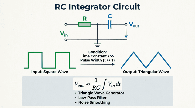
The RC differentiator is essentially the opposite of the RC integrator. While an integrator smooths and averages signals, a differentiator emphasizes rapid changes and edges. This makes it invaluable for applications like edge detection in digital circuits, pulse sharpening, high-pass filtering, and waveform conversion.
This comprehensive guide will explore the theory, design, and practical applications of RC differentiator circuits, helping you understand when and how to use them effectively in your electronic designs.
What is an RC Differentiator?
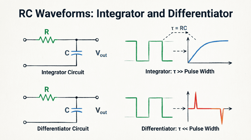
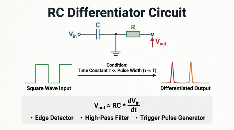
An RC differentiator is a series RC circuit where the output is taken across the resistor. When the time constant $\tau = RC$ is much smaller than the input signal’s period ($\tau \ll T$), the circuit performs mathematical differentiation, converting triangular waves to square waves and producing sharp spikes at signal transitions.
The Theory of Differentiation in RC Circuits
Mathematical Foundation
Differentiation is the process of finding the instantaneous rate of change of a function. Mathematically, the derivative of a function $v_{in}(t)$ with respect to time is:
$v_{out}(t) = RC \frac{dv_{in}(t)}{dt}$
In an RC circuit, the current through the capacitor is related to the voltage by:
$i = C \frac{dv_c}{dt}$
Since the output is taken across the resistor, and $v_{out} = iR$, we get:
$v_{out} = R \times C \frac{dv_c}{dt}$
When the capacitor voltage approximately equals the input voltage ($v_c \approx v_{in}$), we have:
$v_{out}(t) \approx RC \frac{dv_{in}(t)}{dt}$
This shows that the output voltage is proportional to the derivative (rate of change) of the input voltage!
Circuit Configuration
An RC differentiator consists of:
- Capacitor (C) in series with the input
- Resistor (R) connected to ground
- Output taken across the resistor
This configuration is identical to a high-pass RC filter, but we analyze it differently—focusing on its differentiation properties rather than its frequency response.
The Differentiation Condition
For an RC circuit to act as a good differentiator, it must satisfy the differentiation condition:
$\tau = RC \ll T$ or $\tau \ll t_r$
Where:
- $\tau$ = Time constant
- T = Period of the input signal
- $t_r$ = Rise time of the input signal
Rule of Thumb: For good differentiation, $\tau$ should be at least 10 times smaller than the rise time ($\tau \le 0.1 t_r$).
Why This Condition Works
When $\tau \ll t_r$:
- The capacitor charges and discharges very quickly
- The capacitor voltage $v_c$ closely follows the input voltage $v_{in}$
- The current is approximately $i \approx C \frac{dv_{in}}{dt}$
- The output voltage across the resistor is $v_{out} = iR \approx RC \frac{dv_{in}}{dt}$
If $\tau$ is too large, the capacitor cannot respond quickly enough to input changes, and the circuit no longer performs accurate differentiation.
Quick Answer: When does an RC circuit act as a differentiator?
An RC circuit acts as a differentiator when the time constant $\tau = RC$ is much smaller than the input signal rise time (typically $\tau \le 0.1 t_r$). Under this condition, the capacitor responds quickly to input changes, and the output voltage across the resistor is proportional to the derivative of the input voltage.
RC Differentiator Response to Different Waveforms
Triangular Wave Input → Square Wave Output
This is the most common and useful application of an RC differentiator.
Input: Triangular wave with linear rising and falling ramps
Output: Square wave
How it works:
- During the rising ramp, the input has a constant positive slope, producing a constant positive output
- During the falling ramp, the input has a constant negative slope, producing a constant negative output
- The result is a square waveform
Mathematical Analysis:
For a triangular wave with slope $m$ (volts per second):
During rising ramp:
$v_{out} = RC \frac{d}{dt}(mt) = RC \times m$
During falling ramp:
$v_{out} = RC \frac{d}{dt}(-mt) = -RC \times m$
The output amplitude is proportional to both the time constant and the slope of the input!
Square Wave Input → Sharp Spikes Output
Input: Square wave with instantaneous transitions
Output: Positive and negative spikes
How it works:
- At the rising edge, the input changes instantaneously (infinite slope theoretically), producing a sharp positive spike
- During the flat portions, the slope is zero, so the output is zero
- At the falling edge, the input changes instantaneously in the negative direction, producing a sharp negative spike
Practical Consideration:
Real square waves have finite rise and fall times, so the spikes have finite amplitude:
$V_{spike} \approx RC \times \frac{V_{in}}{t_r}$
Where $t_r$ is the rise time of the square wave.
Sine Wave Input → Phase-Shifted Cosine Output
Input: $v_{in}(t) = V_m \sin(\omega t)$
Output: $v_{out}(t) = RC \times \omega V_m \cos(\omega t)$
The differentiator converts a sine wave into a cosine wave (90° phase lead) with amplitude proportional to frequency. This is the basis for:
- Phase shifters
- Frequency multipliers
- High-pass filtering
Pulse Input → Bipolar Spikes
Input: Isolated pulse
Output: Positive spike at leading edge, negative spike at trailing edge
This is useful for:
- Edge detection
- Trigger generation
- Pulse sharpening
Design Considerations for RC Differentiators
Choosing the Time Constant
The time constant $\tau = RC$ is the most critical design parameter.
For Square Wave Differentiation:
- Maximum: $\tau \le 0.1 t_r$ (for reasonable differentiation)
- Better: $\tau \le 0.01 t_r$ (for excellent differentiation)
- Trade-off: Smaller $\tau$ means sharper spikes but lower amplitude
Example:
For a square wave with rise time $t_r = 1$ μs:
- Maximum $\tau = 0.1 \times 1 \text{ μs} = 100 \text{ ns}$
- Better $\tau = 0.01 \times 1 \text{ μs} = 10 \text{ ns}$
Selecting R and C Values
Once you’ve chosen $\tau$, you need to select specific R and C values. Consider:
1. Capacitor Constraints:
- Available standard values
- Parasitic inductance (use small capacitors for high-speed applications)
- Voltage rating (must exceed maximum input voltage)
- Type: Use ceramic or film capacitors for fast response
2. Resistor Constraints:
- Available standard values
- Power dissipation during spikes
- Loading effect on the source
- Noise considerations
Typical Ranges:
- R: 100 Ω to 100 kΩ
- C: 10 pF to 1 μF
Example Design:
For $\tau = 100$ ns:
- Option 1: R = 10 kΩ, C = 10 pF
- Option 2: R = 1 kΩ, C = 100 pF
- Option 3: R = 100 kΩ, C = 1 pF
Choose based on availability, source impedance, and load requirements.
Loading Effects
The differentiator output must drive the next stage of the circuit. If the load resistance $R_L$ is too small, it will load the resistor and reduce the output amplitude.
Rule: $R_L \ge 10R$ (load resistance should be at least 10 times the series resistor)
If this condition cannot be met, use a voltage follower (op-amp buffer) between the differentiator and the load.
High-Frequency Noise Amplification
Differentiators inherently amplify high-frequency components, including noise. This can be problematic in noisy environments.
Solutions:
- Add a small capacitor in parallel with the resistor to limit high-frequency gain
- Use a series resistor with the capacitor to limit high-frequency response
- Use active differentiators with op-amps that include frequency compensation
Practical Examples and Calculations
Example 1: Square Wave Edge Detector
Problem: Design an RC differentiator to detect the edges of a 5V square wave with a rise time of 100 ns. The output spikes should be at least 2V amplitude.
Solution:
Given:
- $V_{in} = 5$V
- $t_r = 100$ ns = $100 \times 10^{-9}$ s
- Desired $V_{spike} \ge 2$V
Step 1: Calculate required time constant from spike amplitude
$V_{spike} \approx RC \times \frac{V_{in}}{t_r} = \tau \times \frac{V_{in}}{t_r}$
$\tau \ge \frac{V_{spike} \times t_r}{V_{in}} = \frac{2 \times 100 \times 10^{-9}}{5} = 40 \times 10^{-9} \text{ s} = 40 \text{ ns}$
Step 2: Verify differentiation condition
For good differentiation: $\tau \le 0.1 t_r = 0.1 \times 100 \text{ ns} = 10 \text{ ns}$
Conflict: We need $\tau \ge 40$ ns for amplitude but $\tau \le 10$ ns for good differentiation.
Solution: We must compromise. Let’s use $\tau = 10$ ns for good differentiation and accept lower spike amplitude:
$V_{spike} = 10 \times 10^{-9} \times \frac{5}{100 \times 10^{-9}} = 0.5$V
If we need 2V spikes, we need to amplify the output or use a different approach.
Step 3: Choose R and C
$\tau = 10$ ns = $10 \times 10^{-9}$ s
Option: R = 1 kΩ, C = 10 pF
$\tau = 1,000 \times 10 \times 10^{-12} = 10 \times 10^{-9}$ s ✓
Result: Use R = 1 kΩ and C = 10 pF for good differentiation, producing 0.5V spikes. Add an amplifier if 2V spikes are required.
Example 2: Triangular to Square Wave Converter
Problem: Design an RC differentiator to convert a triangular wave with amplitude ±5V and frequency 1 kHz into a square wave. The triangular wave has a rise time of 0.5 ms.
Solution:
Given:
- Triangular wave: ±5V amplitude
- $f = 1000$ Hz
- $t_r = 0.5$ ms = $0.5 \times 10^{-3}$ s (time to go from -5V to +5V)
Step 1: Calculate the slope of the triangular wave
Slope $m = \frac{\Delta V}{\Delta t} = \frac{10\text{V}}{0.5 \times 10^{-3}\text{s}} = 20,000$ V/s
Step 2: Choose time constant for good differentiation
$\tau \le 0.1 t_r = 0.1 \times 0.5 \text{ ms} = 50 \text{ μs}$
Let’s use $\tau = 50$ μs = $50 \times 10^{-6}$ s
Step 3: Calculate output amplitude
$V_{out} = RC \times m = \tau \times m$
$V_{out} = 50 \times 10^{-6} \times 20,000 = 1$V
The output will be a square wave alternating between +1V and -1V.
Step 4: Choose R and C
$\tau = 50$ μs = $50 \times 10^{-6}$ s
Option: R = 50 kΩ, C = 1 nF
$\tau = 50,000 \times 1 \times 10^{-9} = 50 \times 10^{-6}$ s ✓
Result: Use R = 50 kΩ and C = 1 nF to convert the triangular wave to a ±1V square wave.
Example 3: Pulse Sharpening Circuit
Problem: A pulse signal with 10V amplitude and 1 μs rise time needs to be sharpened for triggering a digital circuit. Design an RC differentiator that produces sharp spikes with amplitude at least 3V.
Solution:
Given:
- $V_{in} = 10$V
- $t_r = 1$ μs = $1 \times 10^{-6}$ s
- Desired $V_{spike} \ge 3$V
Step 1: Calculate required time constant
$V_{spike} \approx \tau \times \frac{V_{in}}{t_r}$
$\tau \ge \frac{V_{spike} \times t_r}{V_{in}} = \frac{3 \times 1 \times 10^{-6}}{10} = 0.3 \times 10^{-6} \text{ s} = 300 \text{ ns}$
Step 2: Verify differentiation condition
$\tau \le 0.1 t_r = 0.1 \times 1 \text{ μs} = 100 \text{ ns}$
Conflict: We need $\tau \ge 300$ ns for amplitude but $\tau \le 100$ ns for good differentiation.
Solution: Use $\tau = 100$ ns and accept lower amplitude, or add amplification.
With $\tau = 100$ ns:
$V_{spike} = 100 \times 10^{-9} \times \frac{10}{1 \times 10^{-6}} = 1$V
Step 3: Choose R and C
$\tau = 100$ ns = $100 \times 10^{-9}$ s
Option: R = 10 kΩ, C = 10 pF
$\tau = 10,000 \times 10 \times 10^{-12} = 100 \times 10^{-9}$ s ✓
Result: Use R = 10 kΩ and C = 10 pF to produce 1V spikes. Add a comparator or amplifier to generate clean 3V digital triggers.
Applications of RC Differentiators
1. Edge Detection
Digital Circuits:
- Detect rising and falling edges of digital signals
- Generate trigger pulses for flip-flops and counters
- Create clock signals from data transitions
Communication Systems:
- Extract timing information from data streams
- Synchronize receivers to transmitters
- Clock recovery circuits
2. Pulse Sharpening
Radar Systems:
- Sharpen return pulses for better resolution
- Improve target detection accuracy
Digital Electronics:
- Convert slow-rise pulses to sharp edges
- Improve noise immunity
- Reduce propagation delay
3. Waveform Conversion
Function Generators:
- Convert triangular waves to square waves
- Generate pulse trains from ramps
- Create complex waveforms
Signal Processing:
- Extract high-frequency components
- Emphasize rapid changes
- Pre-emphasis circuits
4. High-Pass Filtering
Audio Applications:
- Remove low-frequency rumble
- Block DC offset
- AC coupling between stages
Instrumentation:
- Remove drift and low-frequency noise
- Extract AC signals from DC bias
- Coupling capacitors in amplifiers
5. Rate-of-Change Detection
Control Systems:
- Derivative control in PID controllers
- Detect rapid changes in sensor signals
- Predictive control algorithms
Protection Circuits:
- Detect overcurrent conditions (rapid current rise)
- Overvoltage protection
- Fault detection
Limitations and Practical Issues
1. Noise Amplification
Differentiators amplify high-frequency noise, which can overwhelm the desired signal.
Solutions:
- Add a small capacitor in parallel with R to limit bandwidth
- Use shielding and proper grounding
- Filter the input signal before differentiation
2. Limited Output Amplitude
The output amplitude is proportional to $\tau$, but $\tau$ must be small for good differentiation.
Solutions:
- Use an amplifier after the differentiator
- Use active differentiators with op-amps
- Accept lower amplitude and use sensitive detectors
3. Component Parasitics
At high frequencies, capacitor inductance and resistor capacitance affect performance.
Solutions:
- Use surface-mount components
- Choose components rated for high-frequency operation
- Keep leads short
4. Loading Effects
The output impedance of a differentiator is approximately R, which can load the next stage.
Solutions:
- Use a voltage follower buffer
- Choose R small enough to drive the load
- Use active differentiators with low output impedance
RC differentiators are powerful circuits that perform the mathematical operation of differentiation on electrical signals. By taking the output across the resistor in a series RC circuit with a short time constant, we can detect edges, sharpen pulses, convert waveforms, and extract high-frequency components.
Key takeaways from this guide include:
- Differentiation Condition: For accurate differentiation, $\tau = RC \le 0.1 t_r$ (time constant at most 10% of the rise time)
- Output Relationship: $v_{out}(t) \approx RC \frac{dv_{in}(t)}{dt}$ (output is proportional to the derivative of input)
- Triangular Wave Response: Converts triangular waves to square waves with amplitude proportional to slope and $\tau$
- Square Wave Response: Produces sharp positive and negative spikes at transitions, useful for edge detection
- Design Trade-offs: Smaller $\tau$ gives better differentiation but lower output amplitude
- Applications: Edge detection, pulse sharpening, waveform conversion, high-pass filtering, and rate-of-change detection
- Limitations: Noise amplification, limited amplitude, component parasitics, and loading effects must be managed
The RC differentiator is a fundamental building block in analog and digital electronics. While modern systems often use active differentiators with op-amps or digital signal processing for better performance, understanding the passive RC differentiator provides essential insight into the principles of differentiation, edge detection, and high-pass filtering. Whether you’re designing a simple trigger circuit or a complex signal processing system, the RC differentiator remains a valuable tool in your electrical engineering toolkit.