RC Discharging Circuit
RC Discharging Circuit: Complete Guide to Capacitor Discharge Analysis
Introduction to RC Discharging Circuits
While RC charging circuits describe how capacitors accumulate energy, RC discharging circuits explain how that stored energy is released. When a charged capacitor is connected across a resistor, it doesn’t lose its voltage instantly, it discharges gradually following a predictable exponential decay curve.
Understanding capacitor discharge is essential for designing:
- Camera flash circuits
- Defibrillators and medical equipment
- Power supply bleeder circuits
- Timing and delay circuits
- Energy storage systems
- Safety discharge mechanisms
The principles governing discharge are closely related to charging but with key differences in direction, initial conditions, and final states. This comprehensive guide will explore every aspect of RC discharging circuits, from fundamental physics to advanced applications and safety considerations.
What is an RC Discharging Circuit?
An RC discharging circuit consists of a charged capacitor connected to a resistor. When the circuit is closed, the capacitor discharges through the resistor, with voltage decreasing from its initial value to zero following the equation: Vc(t) = V₀e^(-t/RC), where V₀ is the initial voltage and RC is the time constant τ.
Understanding the RC Discharging Process
Circuit Configuration
A basic RC discharging circuit consists of:
- Charged Capacitor (C): Initially charged to voltage V₀
- Resistor (R): Provides the discharge path
- Switch: Controls when discharge begins
Unlike the charging circuit, there is no voltage source during discharge—the capacitor itself acts as the energy source.
The Physics of Capacitor Discharging
When the switch closes at time t=0, the following occurs:
Initial Condition (t=0):
- Capacitor is fully charged: Vc = V₀
- Maximum voltage appears across resistor: Vr = V₀
- Maximum discharge current flows: I = V₀/R
- Current flows opposite to charging direction
During Discharging (0 < t < ∞):
- Charge leaves the capacitor plates
- Capacitor voltage Vc decreases
- Voltage across resistor Vr decreases (since Vr = Vc)
- Discharge current I decreases
- Energy is dissipated as heat in the resistor
Final Condition (t → ∞):
- Capacitor is fully discharged: Vc = 0V
- No voltage across resistor: Vr = 0V
- Current stops flowing: I = 0
- All stored energy has been dissipated
Energy Dissipation
During discharge, the energy initially stored in the capacitor’s electric field is converted to heat in the resistor:
Initial Energy: $E = \frac{1}{2}CV_0^2$
This energy is completely dissipated as heat during the discharge process.
How long does it take to discharge a capacitor?
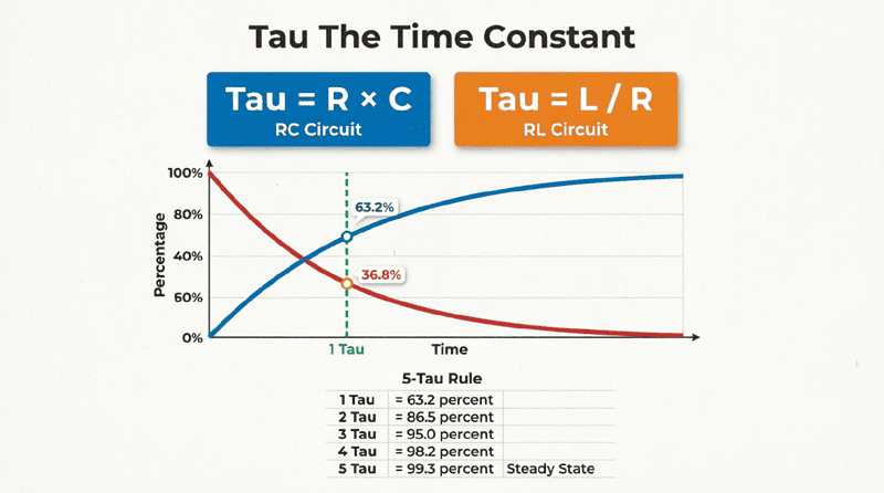
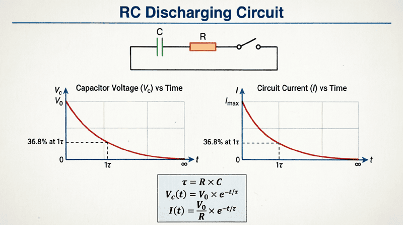
Like charging, a capacitor theoretically takes infinite time to fully discharge, but practically: After 1 time constant (τ = RC), voltage drops to 36.8% of initial. After 5 time constants (5τ), voltage drops to 0.7% and is considered fully discharged for most practical purposes.
Mathematical Analysis of RC Discharging
The Discharging Equation
The voltage across a discharging capacitor as a function of time is given by:
$V_c(t) = V_0 e^{-t/\tau}$
Where:
- Vc(t) = Capacitor voltage at time t (volts)
- V₀ = Initial capacitor voltage at t=0 (volts)
- t = Time elapsed since discharge began (seconds)
- τ = Time constant = RC (seconds)
- e = Euler’s number ≈ 2.71828
Deriving the Discharging Equation
Let’s derive this equation using Kirchhoff’s Voltage Law (KVL):
Step 1: Apply KVL
Around the loop: $V_R + V_C = 0$
Step 2: Express in terms of current
$iR + V_C = 0$
Step 3: Relate current to capacitor voltage
Since $i = C\frac{dV_C}{dt}$ and current flows out of capacitor:
$i = -C\frac{dV_C}{dt}$
$-RC\frac{dV_C}{dt} + V_C = 0$
Step 4: Rearrange
$RC\frac{dV_C}{dt} = -V_C$
$\frac{dV_C}{V_C} = -\frac{dt}{RC}$
Step 5: Integrate both sides
$\int_{V_0}^{V_C} \frac{dV}{V} = -\int_0^t \frac{dt}{RC}$
$\ln(V_C) – \ln(V_0) = -\frac{t}{RC}$
$\ln\left(\frac{V_C}{V_0}\right) = -\frac{t}{RC}$
Step 6: Solve for Vc
$\frac{V_C}{V_0} = e^{-t/RC}$
$V_C = V_0 e^{-t/RC}$
Current During Discharging
The discharge current also follows an exponential decay:
$i(t) = \frac{V_0}{R}e^{-t/\tau}$
Where:
- i(t) = Current at time t (amperes)
- V₀/R = Initial current at t=0 (maximum discharge current)
Important: The current direction is opposite to the charging current direction.
At t=0: i(0) = V₀/R (maximum)
At t→∞: i(∞) = 0 (no current)
Voltage Across the Resistor
Since $V_R = iR$:
$V_R(t) = V_0 e^{-t/\tau}$
Note that $V_R(t) = V_C(t)$ during discharge—they’re equal and decay together.
The Time Constant in Discharging
Definition and Significance
The time constant τ = RC has the same meaning in discharging as in charging:
$\tau = RC$
During discharge, τ represents:
- The time required for voltage to decay to 36.8% of initial value
- The time required for current to decay to 36.8% of initial value
- A measure of discharge speed
Discharge Progress at Key Time Intervals
| Time | % of V₀ | Capacitor Voltage | Status |
|---|---|---|---|
| t = 0 | 100% | V₀ | Discharge begins |
| t = τ | 36.8% | 0.368V₀ | One time constant |
| t = 2τ | 13.5% | 0.135V₀ | |
| t = 3τ | 5.0% | 0.050V₀ | |
| t = 4τ | 1.8% | 0.018V₀ | |
| t = 5τ | 0.7% | 0.007V₀ | Practically fully discharged |
Rule of Thumb: After 5 time constants (5τ), the capacitor is considered fully discharged for most practical applications.
Comparing Charging vs. Discharging
| Parameter | Charging | Discharging |
|---|---|---|
| Initial Voltage | 0V | V₀ |
| Final Voltage | Vs | 0V |
| Equation | Vc = Vs(1 – e^(-t/τ)) | Vc = V₀e^(-t/τ) |
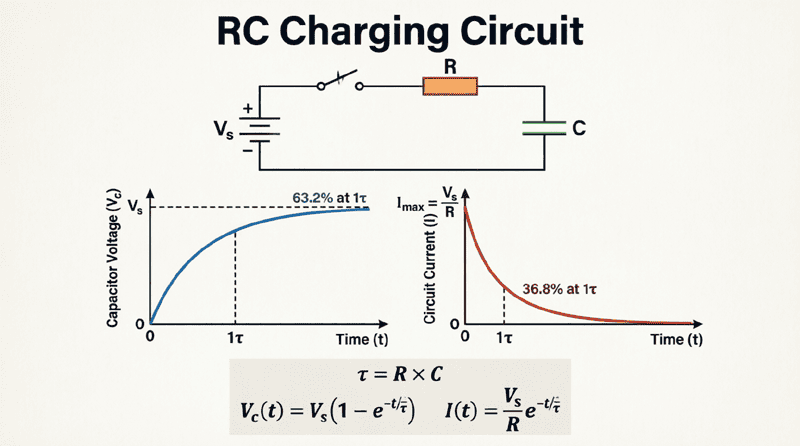
| At t = τ | 63.2% of Vs | 36.8% of V₀ |
| At t = 5τ | 99.3% of Vs | 0.7% of V₀ |
| Time Constant | τ = RC | τ = RC (same) |
What is the difference between charging and discharging?
During charging, voltage increases from 0 to Vs following Vc = Vs(1 – e^(-t/τ)). During discharging, voltage decreases from V₀ to 0 following Vc = V₀e^(-t/τ). Both use the same time constant τ = RC, but charging reaches 63.2% in one τ while discharging drops to 36.8% in one τ.
Practical Examples and Calculations
Example 1: Basic Discharge Calculation
Problem: A 100 μF capacitor is charged to 50V and then discharged through a 10 kΩ resistor. Calculate:
- The time constant
- The capacitor voltage after 2 seconds
- The time required to discharge to 5V
- The initial discharge current
Solution:
Given:
- V₀ = 50V
- R = 10,000 Ω
- C = 100 × 10^-6 F
1. Time Constant:
τ = RC = (10,000)(100 × 10^-6) = 1 second
2. Capacitor Voltage at t = 2s:
Vc = V₀e^(-t/τ) = 50e^(-2/1)
Vc = 50e^(-2) = 50 × 0.135 = 6.75V
3. Time to Reach 5V:
5 = 50e^(-t/1)
0.1 = e^(-t)
ln(0.1) = -t
t = -ln(0.1) = 2.303 seconds
4. Initial Current (t=0):
I₀ = V₀/R = 50/10,000 = 5 mA
Example 2: Safety Discharge Design
Problem: A high-voltage power supply uses a 2000 μF capacitor charged to 400V. Design a bleeder resistor to discharge the capacitor to less than 50V within 30 seconds for safety. What is the minimum power rating required for the resistor?
Solution:
Given:
- V₀ = 400V
- Vc = 50V at t = 30s
- C = 2000 × 10^-6 F
- Find R and power rating
Using the discharge equation:
50 = 400e^(-30/τ)
0.125 = e^(-30/τ)
ln(0.125) = -30/τ
-2.079 = -30/τ
τ = 30/2.079 = 14.43 seconds
Since τ = RC:
R = τ/C = 14.43/(2000 × 10^-6) = 7,215 Ω
Use standard value: R = 7.5 kΩ
Verify:
τ = 7,500 × 2000 × 10^-6 = 15 seconds
At t = 30s: Vc = 400e^(-30/15) = 400e^(-2) = 54.1V ✓ (close enough)
Power Rating:
Maximum power occurs at t=0:
Pmax = V₀²/R = 400²/7,500 = 160,000/7,500 = 21.3W
Use resistor rated for 25W or higher for safety margin.
Example 3: Energy and Power Analysis
Problem: A 500 μF capacitor charged to 100V is discharged through a 2 kΩ resistor. Calculate:
- Initial energy stored
- Initial power dissipated
- Time when power drops to half its initial value
Solution:
Given:
- V₀ = 100V
- C = 500 × 10^-6 F
- R = 2,000 Ω
- τ = RC = 2,000 × 500 × 10^-6 = 1 second
1. Initial Energy:
E = ½CV₀² = ½(500 × 10^-6)(100)²
E = ½(500 × 10^-6)(10,000) = 2.5 J
2. Initial Power:
P₀ = V₀²/R = 100²/2,000 = 10,000/2,000 = 5W
3. Time for Power to Drop to Half:
Power at time t: P(t) = Vc(t)²/R = (V₀e^(-t/τ))²/R
We want P(t) = P₀/2:
(V₀e^(-t/τ))²/R = (V₀²/R)/2
e^(-2t/τ) = 0.5
-2t/τ = ln(0.5) = -0.693
t = 0.693τ/2 = 0.3465τ
With τ = 1s:
t = 0.347 seconds
Graphical Representation of Discharging
Voltage vs. Time Curve
The capacitor voltage follows an exponential decay:
- Starts at V₀ when t=0
- Decreases rapidly at first
- Gradually slows as it approaches 0V
- Asymptotically approaches 0V (never quite reaches it theoretically)
Current vs. Time Curve
The discharge current also follows an exponential decay:
- Starts at maximum (V₀/R) when t=0
- Decreases in the same proportion as voltage
- Approaches zero as capacitor discharges
Key Points on the Curves
At t = 0:
- Vc = V₀
- i = V₀/R (maximum)
- Vr = V₀
At t = τ:
- Vc = 0.368V₀
- i = 0.368(V₀/R)
- Vr = 0.368V₀
At t = 5τ:
- Vc = 0.007V₀
- i = 0.007(V₀/R)
- Vr = 0.007V₀
Factors Affecting Discharge Time
Resistance (R)
Increasing R:
- Decreases discharge current
- Increases time constant τ
- Slower discharge
- Lower power dissipation
Decreasing R:
- Increases discharge current
- Decreases time constant τ
- Faster discharge
- Higher power dissipation (may require larger resistor wattage)
Capacitance (C)
Increasing C:
- Stores more charge
- Increases time constant τ
- Slower discharge
- More energy to dissipate
Decreasing C:
- Stores less charge
- Decreases time constant τ
- Faster discharge
- Less energy to dissipate
Initial Voltage (V₀)
Increasing V₀:
- Does NOT affect discharge time (τ is independent of V₀)
- Increases initial current
- Increases initial power dissipation
- Increases energy stored (proportional to V₀²)
Note: The time to discharge to a certain percentage of V₀ is independent of V₀, but the time to reach a specific voltage level does depend on V₀.
Practical Applications
1. Bleeder Resistors
Safety resistors permanently connected across capacitors to discharge them when power is removed:
- Power supply safety
- Preventing electric shock
- Meeting safety regulations
2. Camera Flash Circuits
Capacitors charge slowly, then discharge rapidly through the flash tube:
- Energy storage
- Rapid discharge for bright flash
- Controlled by RC timing
3. Defibrillators
Medical devices that store energy and discharge it through the heart:
- High-voltage capacitors
- Controlled discharge timing
- Life-saving applications
4. Timing Circuits
RC discharge creates precise time delays:
- Monostable multivibrators
- One-shot timers
- Pulse generation
5. Sample and Hold Reset
Discharging capacitors to reset circuits:
- ADC reset
- Circuit initialization
- Signal clearing
6. Snubber Circuits
RC networks that discharge voltage spikes:
- Protecting semiconductors
- Suppressing transients
- Reducing EMI
Safety Considerations
High-Voltage Capacitors
Dangers:
- Capacitors can retain charge for hours or days
- High-voltage capacitors can deliver lethal shocks
- Even after power is removed
Safety Practices:
- Always use bleeder resistors
- Verify discharge with a voltmeter before touching
- Short capacitor terminals with insulated tool
- Wait at least 5 time constants
- Use appropriate PPE (personal protective equipment)
Bleeder Resistor Design
Requirements:
- Low enough resistance for safe discharge time
- High enough resistance to avoid excessive power dissipation during normal operation
- Adequate power rating
- Reliable construction
Typical Values:
- Discharge time: 1-5 minutes to safe voltage
- Resistance: 10 kΩ to 1 MΩ
- Power rating: 1W to 10W depending on voltage
Discharge Time Calculation for Safety
Example: A 1000 μF capacitor at 300V must discharge to <50V within 60 seconds.
Required τ:
50 = 300e^(-60/τ)
0.167 = e^(-60/τ)
τ = 60/(-ln(0.167)) = 60/1.79 = 33.5s
R = τ/C = 33.5/(1000 × 10^-6) = 33.5 kΩ
Use 33 kΩ bleeder resistor.
Common Mistakes and Troubleshooting
Mistake 1: No Bleeder Resistor
Problem: Capacitor remains charged after power-off, creating shock hazard.
Solution: Always install bleeder resistors across high-voltage capacitors.
Mistake 2: Wrong Resistor Power Rating
Problem: Resistor overheats and fails during discharge.
Solution: Calculate maximum power: Pmax = V₀²/R and use resistor rated for at least 2× this value.
Mistake 3: Assuming Instant Discharge
Problem: Touching capacitor terminals too soon after power-off.
Solution: Always wait at least 5τ and verify with voltmeter.
Troubleshooting Tips
Capacitor not discharging:
- Check for open bleeder resistor
- Verify resistor value
- Check for open circuit connections
Discharging too slowly:
- Check resistor value (may be too high)
- Verify capacitor value (may be too large)
- Check for capacitor leakage
Discharging too quickly:
- Check resistor value (may be too low)
- Verify capacitor value (may be too small)
- Check for parallel discharge paths
RC discharging circuits describe how capacitors release stored energy through resistors, following an exponential decay pattern. The discharge behavior, characterized by the time constant τ = RC, is fundamental to timing circuits, safety systems, and energy management applications.
Key takeaways from this guide include:
- Discharge Equation: Vc(t) = V₀e^(-t/RC) describes capacitor voltage during discharge
- Time Constant: τ = RC determines discharge speed; after one τ, voltage drops to 36.8% of V₀
- Practical Full Discharge: After 5τ, capacitor is 99.3% discharged (0.7% remaining)
- Current Decay: Discharge current starts at V₀/R and decays exponentially to zero
- Energy Dissipation: All stored energy (½CV₀²) is converted to heat in the resistor
- Safety: Bleeder resistors are essential for high-voltage circuits to prevent shock hazards
- Applications: Camera flashes, defibrillators, timing circuits, and safety discharge systems all rely on RC discharge principles
Understanding RC discharging circuits is crucial for designing safe, reliable electronic systems. Whether you’re implementing safety features in power supplies, designing timing circuits, or working with energy storage systems, the principles of RC discharge are essential tools in your electrical engineering toolkit.