Inductors in Parallel
Inductors in Parallel: Complete Guide to Equivalent Inductance and Current Division
Introduction to Inductors in Parallel
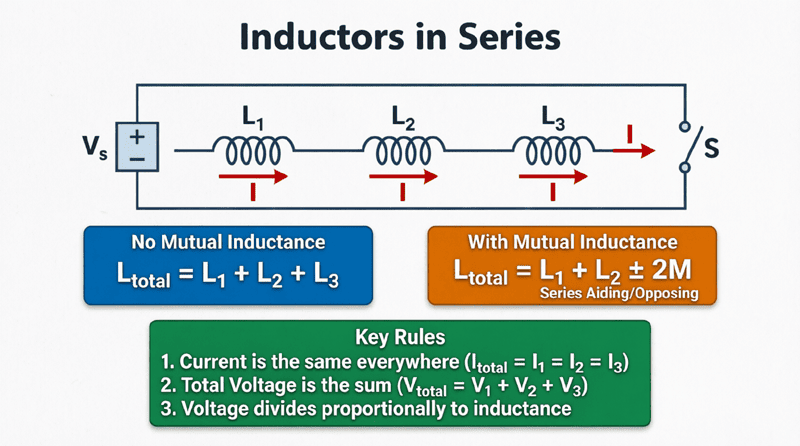
In electrical circuit design, connecting components in parallel is a fundamental technique used to alter the overall electrical characteristics of a network. While connecting inductors in series increases the total inductance, connecting inductors in parallel achieves the exact opposite effect: it decreases the total equivalent inductance.
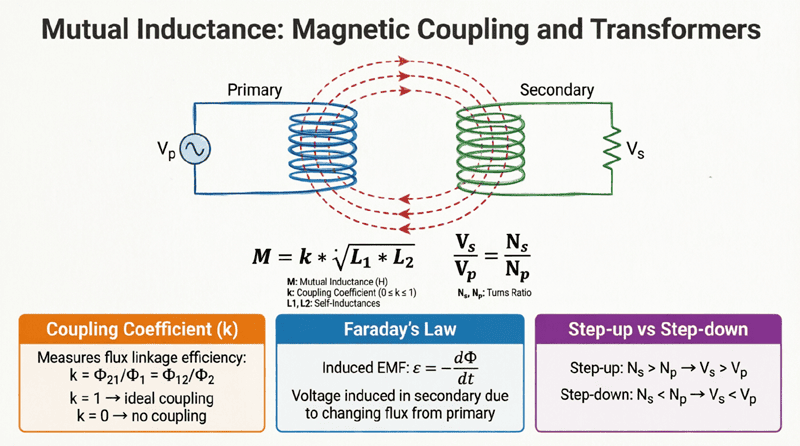
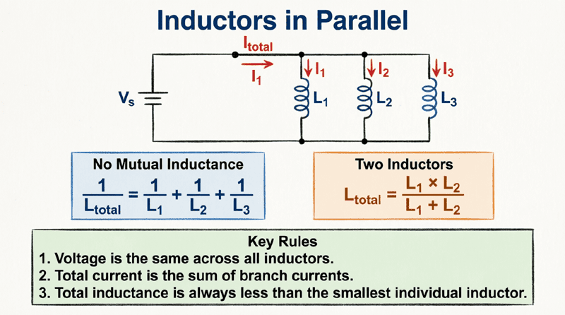
When inductors are connected in parallel, they are arranged across the same two nodes, meaning the exact same voltage is applied across each inductor simultaneously. However, the total current supplied by the source is divided among the parallel branches. Just like in series circuits, calculating the total inductance of a parallel network is straightforward if the coils are magnetically isolated. But if the coils are placed close together, mutual inductance complicates the math, requiring us to account for whether their magnetic fields are aiding or opposing each other.
Understanding how to calculate the equivalent inductance of parallel-connected coils, as well as how current divides among them, is essential for designing complex filters, impedance matching networks, and high-current power supplies. This comprehensive guide will explore the physics, mathematical derivations, and practical calculations for inductors connected in parallel.
How do you calculate inductors in parallel?
If there is no magnetic coupling between the inductors, the reciprocal of the total equivalent inductance is the sum of the reciprocals of the individual inductances: $1/L_{eq} = 1/L_1 + 1/L_2 + …$. The total inductance in a parallel circuit is always less than the value of the smallest individual inductor.
Inductors in Parallel Without Mutual Inductance
Let’s begin with the most common scenario: multiple inductors connected in parallel where they are physically spaced far apart or magnetically shielded, ensuring their magnetic fields do not interact. In this case, the mutual inductance ($M$) between them is zero.
The Physics of Parallel Inductors
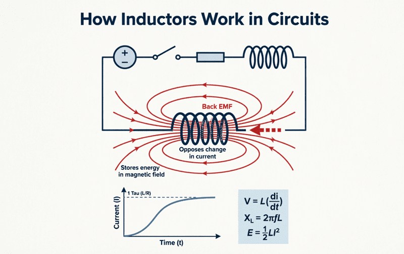
When a voltage ($V$) is applied across a parallel circuit, that exact same voltage is applied across every inductor in the network. According to the fundamental inductor equation, the voltage across an inductor is proportional to the rate of change of current through it:
$V = L \frac{di}{dt}$
Rearranging this to solve for the rate of change of current gives us:
$\frac{di}{dt} = \frac{V}{L}$
According to Kirchhoff’s Current Law (KCL), the total current ($I_{total}$) entering the parallel node is the sum of the individual branch currents. Therefore, the rate of change of the total current must equal the sum of the rates of change of the individual branch currents:
$\frac{di_{total}}{dt} = \frac{di_1}{dt} + \frac{di_2}{dt} + \frac{di_3}{dt}$
Substituting the voltage equation into KCL, we get:
$\frac{V}{L_{eq}} = \frac{V}{L_1} + \frac{V}{L_2} + \frac{V}{L_3}$
Since the voltage ($V$) is common to all terms, we can divide it out, arriving at the fundamental formula for uncoupled parallel inductors:
$\frac{1}{L_{eq}} = \frac{1}{L_1} + \frac{1}{L_2} + \frac{1}{L_3} + … + \frac{1}{L_n}$
To find the total equivalent inductance ($L_{eq}$), you simply take the reciprocal of the sum:
$L_{eq} = \frac{1}{\frac{1}{L_1} + \frac{1}{L_2} + \frac{1}{L_3} + …}$
The Product-Over-Sum Shortcut
When dealing with exactly two inductors in parallel, the math simplifies into a highly convenient shortcut known as the “product-over-sum” formula:
$L_{eq} = \frac{L_1 \times L_2}{L_1 + L_2}$
Practical Calculation Example
Problem: Three uncoupled inductors with values of 10 mH, 20 mH, and 30 mH are connected in parallel. Calculate the total equivalent inductance.
Solution:
Using the reciprocal formula:
$\frac{1}{L_{eq}} = \frac{1}{10} + \frac{1}{20} + \frac{1}{30}$
To add these fractions, find a common denominator (which is 60):
$\frac{1}{L_{eq}} = \frac{6}{60} + \frac{3}{60} + \frac{2}{60} = \frac{11}{60}$
Now, take the reciprocal to find $L_{eq}$:
$L_{eq} = \frac{60}{11}$
$L_{eq} \approx 5.45 \text{ mH}$
Observation: Notice that the total equivalent inductance (5.45 mH) is smaller than the smallest individual inductor in the circuit (10 mH). This is a universal rule for all parallel circuits.
Why is parallel inductance always smaller than the smallest inductor?
Connecting inductors in parallel provides multiple paths for the current to flow, making it easier for the total current to change. Just like adding more lanes to a highway reduces traffic resistance, adding parallel inductive paths reduces the total opposition to changing current, resulting in an equivalent inductance lower than the smallest branch.
Inductors in Parallel WITH Mutual Inductance
When two inductors are connected in parallel and placed close enough that their magnetic fields interact, mutual inductance ($M$) must be factored into the calculation. The total equivalent inductance will change depending on whether the magnetic fields reinforce each other (aiding) or cancel each other (opposing).
Calculating the equivalent inductance for coupled parallel inductors requires solving simultaneous differential equations, which results in the following specialized formulas.
1. Parallel Aiding Connection
In a parallel aiding configuration, the coils are connected such that their magnetic fields point in the same direction, reinforcing each other. This increases the overall opposition to current change compared to the uncoupled state.
The formula for parallel aiding is:
$L_{eq(aid)} = \frac{L_1 L_2 – M^2}{L_1 + L_2 – 2M}$
Notice that the denominator subtracts $2M$. Because the denominator is smaller, the resulting $L_{eq}$ is larger.
2. Parallel Opposing Connection
In a parallel opposing configuration, the coils are connected such that their magnetic fields point in opposite directions, canceling each other out. This decreases the overall opposition to current change.
The formula for parallel opposing is:
$L_{eq(opp)} = \frac{L_1 L_2 – M^2}{L_1 + L_2 + 2M}$
Here, the denominator adds $2M$. Because the denominator is larger, the resulting $L_{eq}$ is smaller.
Practical Calculation Example with Mutual Inductance
Problem: Two inductors, $L_1 = 20 \text{ mH}$ and $L_2 = 30 \text{ mH}$, are connected in parallel. They have a mutual inductance of $M = 5 \text{ mH}$. Calculate the total equivalent inductance for both parallel aiding and parallel opposing configurations.
Solution for Parallel Aiding:
$L_{eq(aid)} = \frac{(20 \times 30) – 5^2}{20 + 30 – (2 \times 5)}$
$L_{eq(aid)} = \frac{600 – 25}{50 – 10}$
$L_{eq(aid)} = \frac{575}{40}$
$L_{eq(aid)} = 14.375 \text{ mH}$
Solution for Parallel Opposing:
$L_{eq(opp)} = \frac{(20 \times 30) – 5^2}{20 + 30 + (2 \times 5)}$
$L_{eq(opp)} = \frac{600 – 25}{50 + 10}$
$L_{eq(opp)} = \frac{575}{60}$
$L_{eq(opp)} \approx 9.58 \text{ mH}$
Observation: The parallel aiding configuration yields a higher inductance (14.375 mH) than the parallel opposing configuration (9.58 mH), exactly as the physics of magnetic coupling dictates.
How does mutual inductance affect parallel inductors?
Mutual inductance alters the total equivalent inductance of parallel coils. If the coils are connected in “parallel aiding,” their magnetic fields reinforce each other, increasing the total inductance. If connected in “parallel opposing,” the fields cancel, decreasing the total inductance.
Current Division in Parallel Inductors
Just as current divides among parallel resistors based on their resistance values, alternating current (AC) divides among parallel inductors based on their inductive reactance. In an ideal scenario (ignoring DC resistance), the current divides inversely proportional to the inductance values.
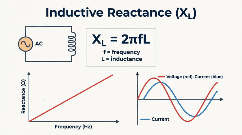
Because a larger inductor presents a higher opposition to changing current (higher inductive reactance, $X_L = 2\pi fL$), less current will flow through it. Conversely, more current will flow through the smaller inductor.
The Current Division Formula:
The current flowing through a specific branch ($I_x$) can be calculated using the total current ($I_{total}$) and the ratio of the equivalent inductance to the branch inductance:
$I_x = I_{total} \times \frac{L_{eq}}{L_x}$
Current Division Example
Problem: A total AC current of 12 Amps flows into a parallel network consisting of two uncoupled inductors: $L_1 = 4 \text{ mH}$ and $L_2 = 12 \text{ mH}$. Calculate the current flowing through each inductor.
Solution:
First, calculate the equivalent inductance using the product-over-sum formula:
$L_{eq} = \frac{4 \times 12}{4 + 12} = \frac{48}{16} = 3 \text{ mH}$
Current through $L_1$ (4 mH):
$I_1 = 12\text{A} \times \frac{3\text{mH}}{4\text{mH}} = 12 \times 0.75 = \mathbf{9 \text{ Amps}}$
Current through $L_2$ (12 mH):
$I_2 = 12\text{A} \times \frac{3\text{mH}}{12\text{mH}} = 12 \times 0.25 = \mathbf{3 \text{ Amps}}$
Verification: $9\text{A} + 3\text{A} = 12\text{A}$. The smaller inductor (4 mH) carries three times as much current as the larger inductor (12 mH), proving the inverse relationship.
Practical Considerations for Parallel Inductors
When implementing parallel inductors in real-world circuit designs, engineers must account for physical limitations that ideal mathematical formulas do not cover.
1. Total Current Handling Capacity
One of the primary reasons engineers connect inductors in parallel is to increase the overall current-handling capability of the circuit. Because the total current is divided among the branches, the maximum safe current for the parallel network is the sum of the individual current ratings of the inductors.
Example: If you parallel two inductors rated for 5 Amps each, the combined branch can safely handle up to 10 Amps (assuming perfect current sharing).
2. DC Resistance (DCR) in Parallel
Real-world inductors are made of wire, meaning they possess inherent DC resistance (DCR). When inductors are connected in parallel, their DC resistances combine using the exact same reciprocal formula used for the inductance:
$\frac{1}{R_{total}} = \frac{1}{R_{DCR1}} + \frac{1}{R_{DCR2}} + … + \frac{1}{R_{DCRn}}$
This is highly beneficial in power supply design. By paralleling inductors, you not only achieve a specific lower inductance value, but you also drastically reduce the total DC resistance, which minimizes $I^2R$ power losses and heat generation.
3. The Danger of Unequal Current Sharing
In theory, current divides perfectly based on inductance. In reality, slight manufacturing tolerances mean no two inductors are exactly identical. Furthermore, if the inductors have different DC resistances, the DC component of the current will not divide equally. If one inductor has a slightly lower DCR, it will hog more of the DC current, potentially causing it to overheat or saturate its magnetic core prematurely. For high-current parallel applications, it is best practice to use inductors from the same manufacturing batch with tightly matched specifications.
Connecting inductors in parallel is a vital technique for reducing overall inductance, lowering DC resistance, and increasing the total current capacity of a circuit. While the mathematics of uncoupled parallel inductors mirror those of parallel resistors, the introduction of mutual inductance adds a layer of complexity that requires careful attention to the physical orientation of the coils.
Key takeaways from this guide include:
- Uncoupled Formula: The reciprocal of the total inductance equals the sum of the reciprocals of the individual inductances ($1/L_{eq} = 1/L_1 + 1/L_2 + …$).
- The Smallest Rule: The total equivalent inductance of a parallel circuit is always less than the value of the smallest individual inductor in the network.
- Coupled Formulas: Mutual inductance ($M$) must be accounted for. Parallel aiding increases total inductance (denominator subtracts $2M$), while parallel opposing decreases it (denominator adds $2M$).
- Current Division: Current divides inversely proportional to the inductance values; smaller inductors carry more current.
- Real-World Benefits: Paralleling inductors reduces total DC resistance (DCR) and increases the overall current-handling capacity of the branch.
Mastering the behavior of inductors in parallel completes the foundational knowledge required to analyze and design complex RLC networks. Whether you are building a low-pass filter, designing a multiphase buck converter, or analyzing a coupled transformer circuit, the principles outlined in this guide are indispensable tools for the electrical engineer.