
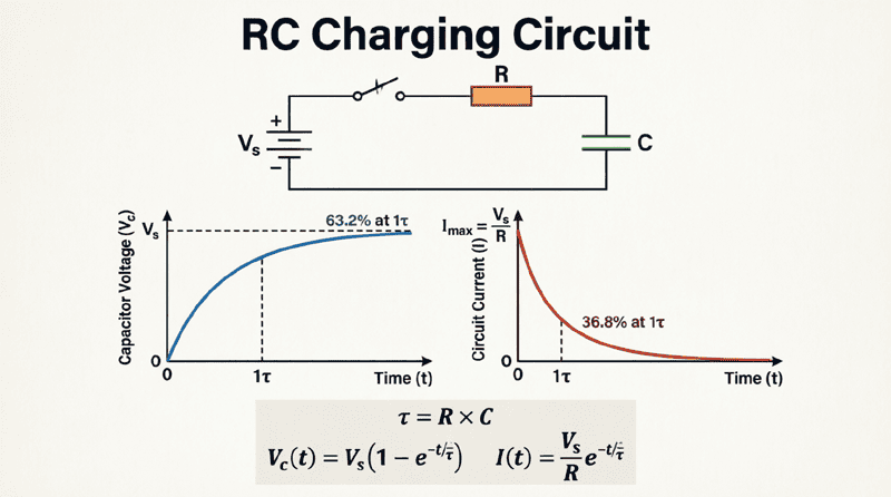
RC Charging Circuit
RC Charging Circuit: Complete Guide to Capacitor Charging Analysis
Introduction to RC Charging Circuits
The RC charging circuit is one of the most fundamental and important circuits in electrical engineering. When a capacitor is connected to a DC voltage source through a resistor, it doesn’t charge instantly—instead, it charges gradually following a predictable exponential curve. Understanding this charging behavior is crucial for designing timing circuits, filters, power supplies, and countless other electronic applications.
From the simple blink of an LED to the complex timing mechanisms in microprocessors, RC charging circuits are everywhere. They control how quickly signals rise, how long delays last, and how energy is stored and released in electronic systems.
This comprehensive guide will explore every aspect of RC charging circuits, from the fundamental physics of capacitor charging to advanced analysis techniques, practical calculations, and real-world applications.
What is an RC Charging Circuit?
An RC charging circuit consists of a resistor (R) and capacitor (C) connected in series with a voltage source. When voltage is applied, the capacitor charges exponentially through the resistor, with the voltage across the capacitor increasing from 0V to the source voltage following the equation: Vc(t) = Vs(1 – e^(-t/RC)), where RC is the time constant τ.
Understanding the RC Charging Process
Circuit Configuration
A basic RC charging circuit consists of three components:
- DC Voltage Source (Vs): Provides the charging voltage
- Resistor (R): Limits the charging current
- Capacitor (C): Stores electrical energy
These components are connected in series, often with a switch to control when charging begins.
The Physics of Capacitor Charging
When the switch closes at time t=0, several things happen simultaneously:
Initial Condition (t=0):
- The capacitor is uncharged: Vc = 0V
- Maximum voltage appears across the resistor: Vr = Vs
- Maximum current flows: I = Vs/R
- The capacitor acts like a short circuit
During Charging (0 < t < ∞):
- Charge accumulates on the capacitor plates
- Capacitor voltage Vc increases
- Voltage across resistor Vr decreases (since Vr = Vs – Vc)
- Charging current I decreases
- The capacitor increasingly opposes the charging current
Final Condition (t → ∞):
- Capacitor is fully charged: Vc = Vs
- No voltage across resistor: Vr = 0V
- Current stops flowing: I = 0
- The capacitor acts like an open circuit
Why Does Charging Take Time?
The resistor limits the rate at which charge can flow onto the capacitor plates. A larger resistance means less current, which means slower charging. Similarly, a larger capacitance means more charge is needed to reach a given voltage, also resulting in slower charging.
This relationship is quantified by the time constant τ = RC, which we’ll explore in detail later.
How long does it take to charge a capacitor?
A capacitor theoretically takes infinite time to fully charge, but practically: After 1 time constant (τ = RC), it reaches 63.2% of the source voltage. After 5 time constants (5τ), it reaches 99.3% and is considered fully charged for most practical purposes.
Mathematical Analysis of RC Charging
The Charging Equation
The voltage across a charging capacitor as a function of time is given by:
$V_c(t) = V_s(1 – e^{-t/\tau})$
Where:
- Vc(t) = Capacitor voltage at time t (volts)
- Vs = Source voltage (volts)
- t = Time elapsed since charging began (seconds)
- τ = Time constant = RC (seconds)
- e = Euler’s number ≈ 2.71828
Deriving the Charging Equation
Let’s derive this equation from first principles using Kirchhoff’s Voltage Law (KVL):
Step 1: Apply KVL
Around the loop: $V_s = V_R + V_C$
Step 2: Express in terms of current
$V_s = iR + V_C$
Step 3: Relate current to capacitor voltage
Since $i = C\frac{dV_C}{dt}$:
$V_s = RC\frac{dV_C}{dt} + V_C$
Step 4: Rearrange
$RC\frac{dV_C}{dt} = V_s – V_C$
$\frac{dV_C}{V_s – V_C} = \frac{dt}{RC}$
Step 5: Integrate both sides
$\int_0^{V_C} \frac{dV}{V_s – V} = \int_0^t \frac{dt}{RC}$
$-\ln(V_s – V_C) + \ln(V_s) = \frac{t}{RC}$
$\ln\left(\frac{V_s}{V_s – V_C}\right) = \frac{t}{RC}$
Step 6: Solve for Vc
$\frac{V_s}{V_s – V_C} = e^{t/RC}$
$V_s – V_C = V_s e^{-t/RC}$
$V_C = V_s(1 – e^{-t/RC})$
Current During Charging
The charging current also follows an exponential decay:
$i(t) = \frac{V_s}{R}e^{-t/\tau}$
Where:
- i(t) = Current at time t (amperes)
- Vs/R = Initial current at t=0 (maximum current)
At t=0: i(0) = Vs/R (maximum)
At t→∞: i(∞) = 0 (no current)
Voltage Across the Resistor
Since $V_R = iR$:
$V_R(t) = V_s e^{-t/\tau}$
The resistor voltage starts at Vs and decays to zero.
The Time Constant (τ)
Definition and Significance
The time constant τ (tau) is the product of resistance and capacitance:
$\tau = RC$
Where:
- τ = Time constant (seconds)
- R = Resistance (ohms, Ω)
- C = Capacitance (farads, F)
The time constant represents:
- The time required for the capacitor to charge to 63.2% of the source voltage
- The time required for the current to decay to 36.8% of its initial value
- A measure of how “fast” or “slow” the circuit responds
Charging Progress at Key Time Intervals
| Time | % of Vs | Capacitor Voltage | Status |
|---|---|---|---|
| t = 0 | 0% | 0V | Charging begins |
| t = τ | 63.2% | 0.632Vs | One time constant |
| t = 2τ | 86.5% | 0.865Vs | |
| t = 3τ | 95.0% | 0.950Vs | |
| t = 4τ | 98.2% | 0.982Vs | |
| t = 5τ | 99.3% | 0.993Vs | Practically fully charged |
Rule of Thumb: After 5 time constants (5τ), the capacitor is considered fully charged for most practical applications.
Calculating Time Constant: Examples
Example 1:
R = 10 kΩ, C = 100 μF
τ = RC = (10,000)(100 × 10^-6) = 1 second
Example 2:
R = 1 kΩ, C = 10 nF
τ = RC = (1,000)(10 × 10^-9) = 10 microseconds
Example 3:
R = 100 Ω, C = 1000 pF
τ = RC = (100)(1000 × 10^-12) = 100 nanoseconds
What is the time constant in an RC circuit?
The time constant τ = RC (resistance × capacitance) measured in seconds. It represents the time for the capacitor to charge to 63.2% of the source voltage. After 5 time constants, the capacitor is 99.3% charged and considered fully charged.
Practical Examples and Calculations
Example 1: Basic Charging Calculation
Problem: A 12V battery is connected to a series RC circuit with R = 2 kΩ and C = 50 μF. The capacitor is initially uncharged. Calculate:
- The time constant
- The capacitor voltage after 0.1 seconds
- The time required to reach 9V
- The initial charging current
Solution:
Given:
- Vs = 12V
- R = 2,000 Ω
- C = 50 × 10^-6 F
1. Time Constant:
τ = RC = (2,000)(50 × 10^-6) = 0.1 seconds
2. Capacitor Voltage at t = 0.1s:
Since t = τ:
Vc = Vs(1 – e^(-t/τ)) = 12(1 – e^(-1))
Vc = 12(1 – 0.368) = 12(0.632) = 7.58V
3. Time to Reach 9V:
9 = 12(1 – e^(-t/0.1))
0.75 = 1 – e^(-t/0.1)
e^(-t/0.1) = 0.25
-t/0.1 = ln(0.25) = -1.386
t = 0.1 × 1.386 = 0.139 seconds
4. Initial Current (t=0):
I₀ = Vs/R = 12/2,000 = 6 mA
Example 2: Design Problem
Problem: Design an RC charging circuit that will charge a capacitor to 8V in 5 milliseconds when connected to a 10V source. If C = 1 μF, what value of R is needed?
Solution:
Given:
- Vs = 10V
- Vc = 8V at t = 5 ms
- C = 1 × 10^-6 F
- Find R
Using the charging equation:
8 = 10(1 – e^(-0.005/τ))
0.8 = 1 – e^(-0.005/τ)
e^(-0.005/τ) = 0.2
-0.005/τ = ln(0.2) = -1.609
τ = 0.005/1.609 = 0.00311 seconds
Since τ = RC:
R = τ/C = 0.00311/(1 × 10^-6) = 3,110 Ω or 3.11 kΩ
Example 3: Current and Power Analysis
Problem: In an RC circuit with Vs = 24V, R = 4 kΩ, and C = 25 μF, calculate:
- Maximum power dissipated in the resistor
- Energy stored in the capacitor when fully charged
- Current after 2 time constants
Solution:
Given:
- Vs = 24V
- R = 4,000 Ω
- C = 25 × 10^-6 F
- τ = RC = 4,000 × 25 × 10^-6 = 0.1 seconds
1. Maximum Power in Resistor:
Occurs at t=0 when current is maximum
I₀ = Vs/R = 24/4,000 = 6 mA
Pmax = I₀²R = (0.006)² × 4,000 = 0.144W or 144 mW
2. Energy Stored (Fully Charged):
When fully charged, Vc = Vs = 24V
Energy = ½CV² = ½(25 × 10^-6)(24)²
Energy = ½(25 × 10^-6)(576) = 7.2 mJ
3. Current at t = 2τ:
i(2τ) = (Vs/R)e^(-2τ/τ) = (24/4,000)e^(-2)
i(2τ) = 0.006 × 0.135 = 0.81 mA
Graphical Representation of Charging
Voltage vs. Time Curve
The capacitor voltage follows an exponential rise:
- Starts at 0V when t=0
- Rises rapidly at first
- Gradually slows as it approaches Vs
- Asymptotically approaches Vs (never quite reaches it theoretically)
Current vs. Time Curve
The charging current follows an exponential decay:
- Starts at maximum (Vs/R) when t=0
- Decreases rapidly at first
- Gradually approaches zero
- Theoretically never reaches zero
Key Points on the Curves
At t = 0:
- Vc = 0V
- i = Vs/R (maximum)
- Vr = Vs
At t = τ:
- Vc = 0.632Vs
- i = 0.368(Vs/R)
- Vr = 0.368Vs
At t = 5τ:
- Vc = 0.993Vs
- i = 0.007(Vs/R)
- Vr = 0.007Vs
Factors Affecting Charging Time
Resistance (R)
Increasing R:
- Decreases charging current
- Increases time constant τ
- Slower charging
- Less power dissipation
Decreasing R:
- Increases charging current
- Decreases time constant τ
- Faster charging
- More power dissipation (may require larger resistor wattage)
Capacitance (C)
Increasing C:
- Stores more charge
- Increases time constant τ
- Slower charging
- More energy storage
Decreasing C:
- Stores less charge
- Decreases time constant τ
- Faster charging
- Less energy storage
Source Voltage (Vs)
Increasing Vs:
- Does NOT affect charging time (τ is independent of Vs)
- Increases final voltage
- Increases initial current
- Increases energy stored
Note: The time to reach a certain percentage of Vs is independent of Vs, but the time to reach a specific voltage level does depend on Vs.
Practical Applications
1. Timing Circuits
RC charging circuits create precise time delays:
- Camera flash timing
- Windshield wiper intervals
- Traffic light sequencing
- Industrial process timing
2. Power Supply Filtering
Capacitors charge through resistors to smooth voltage:
- Ripple reduction
- Voltage regulation
- Noise filtering
3. Soft-Start Circuits
Gradual capacitor charging prevents inrush current:
- Motor starting
- LED dimming
- Audio amplifier protection
4. Sample and Hold Circuits
Capacitors charge to sample voltage levels:
- Analog-to-digital conversion
- Signal processing
- Data acquisition
5. Battery Charging
RC principles apply to battery charging circuits:
- Current limiting
- Voltage monitoring
- Charge time estimation
Common Mistakes and Troubleshooting
Mistake 1: Ignoring Initial Conditions
Problem: Assuming capacitor starts at 0V when it may have residual charge.
Solution: Always discharge capacitors before testing, or account for initial voltage in calculations.
Mistake 2: Wrong Time Constant Units
Problem: Mixing seconds, milliseconds, and microseconds.
Solution: Always convert to base units:
- R in ohms (Ω)
- C in farads (F)
- τ in seconds (s)
Mistake 3: Forgetting the 5τ Rule
Problem: Assuming capacitor is fully charged too early.
Solution: Wait at least 5 time constants for 99.3% charging.
Troubleshooting Tips
Capacitor not charging:
- Check for open circuit
- Verify capacitor polarity (electrolytics)
- Test capacitor for shorts
Charging too fast:
- Check resistor value (may be too low)
- Verify capacitor value (may be too small)
- Check for parallel paths
Charging too slow:
- Check resistor value (may be too high)
- Verify capacitor value (may be too large)
- Check for leakage
Summary and Conclusion
RC charging circuits are fundamental building blocks in electronics, controlling how quickly capacitors accumulate charge when connected to a voltage source. The exponential charging behavior, characterized by the time constant τ = RC, determines the circuit’s response time and is crucial for timing, filtering, and energy storage applications.
Key takeaways from this guide include:
- Charging Equation: Vc(t) = Vs(1 – e^(-t/RC)) describes capacitor voltage during charging
- Time Constant: τ = RC determines charging speed; after one τ, capacitor reaches 63.2% of Vs
- Practical Full Charge: After 5τ, capacitor is 99.3% charged and considered fully charged
- Current Decay: Charging current starts at Vs/R and decays exponentially to zero
- Design Considerations: R and C values affect charging time, power dissipation, and energy storage
- Applications: Timing circuits, filters, soft-start circuits, and power supplies all rely on RC charging principles
Understanding RC charging circuits provides the foundation for analyzing more complex circuits, designing timing mechanisms, and troubleshooting electronic systems. Whether you’re building a simple LED flasher or designing a sophisticated power management system, the principles of RC charging are essential tools in your electrical engineering toolkit.