The Colpitts Oscillator
The Colpitts Oscillator: Complete Guide to Capacitive Feedback LC Circuits
Introduction to the Colpitts Oscillator
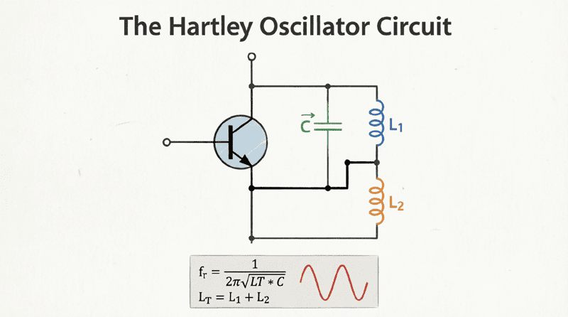
The Colpitts Oscillator, invented by American engineer Edwin H. Colpitts in 1918, stands as one of the most elegant and widely used LC oscillator configurations in modern electronics. While its cousin, the Hartley oscillator, relies on a tapped inductor for feedback, the Colpitts oscillator takes a different approach by utilizing a capacitive voltage divider formed by two series capacitors and a single inductor.
This seemingly simple inversion of the Hartley topology yields significant advantages, particularly in terms of frequency stability and waveform purity. The Colpitts oscillator excels at higher frequencies (VHF and UHF ranges), making it the preferred choice for radio frequency applications, crystal oscillators, and precision signal generation where spectral purity is paramount.
The capacitive feedback network of the Colpitts oscillator offers superior immunity to parasitic inductances and provides better stability against component variations. Additionally, the circuit’s ability to produce a cleaner sinusoidal output with lower harmonic distortion has cemented its地位 as the go-to topology for high-performance RF oscillators.
This comprehensive guide will explore the circuit architecture, mathematical principles, design methodologies, and practical implementations of the Colpitts oscillator, equipping you with the knowledge to design and analyze these essential circuits.
What is a Colpitts Oscillator?
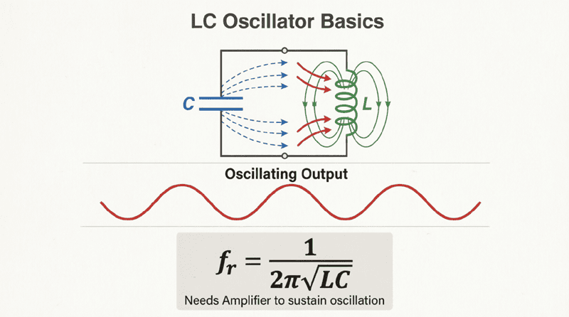
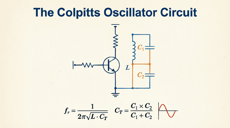
A Colpitts oscillator is an LC oscillator circuit that uses a capacitive voltage divider (two series capacitors) and a single inductor to form the resonant tank circuit. The feedback required for oscillation is derived from the junction of the two capacitors, providing superior frequency stability and waveform purity compared to inductive feedback topologies like the Hartley oscillator.
Circuit Topology and Operation
The Basic Configuration
The Colpitts oscillator shares the same fundamental structure as other LC oscillators but distinguishes itself through its unique tank circuit configuration:
- The Amplifier: As with the Hartley, this is typically a BJT in common-emitter configuration, a FET in common-source, or an operational amplifier. It provides the necessary voltage gain (typically 10-100).
- The Tank Circuit: This is the defining feature of the Colpitts. It consists of:
- A single inductor ($L$)
- Two capacitors in series ($C_1$ and $C_2$)
- The inductor is connected in parallel with the series combination of $C_1$ and $C_2$
- The Feedback Network: The junction between $C_1$ and $C_2$ is tapped and connected to the emitter (for BJT) or source (for FET). This capacitive voltage divider provides the feedback signal to sustain oscillations.
The Capacitive Voltage Divider
The feedback mechanism in the Colpitts oscillator is fundamentally different from the Hartley. Instead of dividing voltage across inductors, it divides voltage across capacitors.
In a capacitive voltage divider, the voltage across each capacitor is inversely proportional to its capacitance. Therefore:
- The smaller capacitor develops a larger voltage across it
- The larger capacitor develops a smaller voltage across it
The feedback fraction ($\beta$) is determined by the ratio of these capacitors:
$\beta = \frac{C_1}{C_2}$ (approximately, for high impedance loads)
This relationship is crucial for design, as it allows precise control over the feedback level by simply adjusting the capacitor ratio.
Phase Shift Mechanism
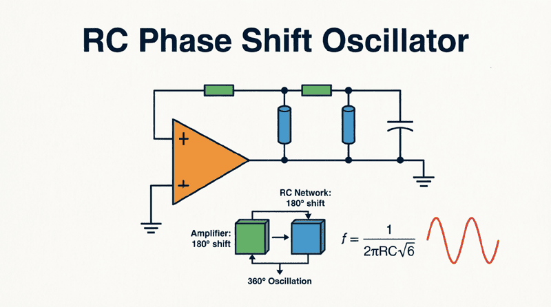
Just like the Hartley oscillator, the Colpitts must satisfy the Barkhausen criterion with a total phase shift of 360° (or 0°):
- Amplifier Phase Shift: The common-emitter (or common-source) amplifier provides 180° phase shift.
- Tank Circuit Phase Shift: The capacitive divider provides the remaining 180° phase shift. Because the capacitors are in series and the tap point is between them, the voltage at the top of $C_1$ (collector side) is 180° out of phase with the voltage at the bottom of $C_2$ (base side) relative to the tap point (emitter/source).
Total: 180° + 180° = 360° ✓
This configuration ensures positive feedback at the resonant frequency.
How does the Colpitts oscillator differ from the Hartley oscillator?
The primary difference is the feedback network: the Colpitts uses a capacitive voltage divider (two capacitors) with a single inductor, while the Hartley uses an inductive voltage divider (two inductors or a tapped coil) with a single capacitor. The Colpitts generally offers better frequency stability and waveform purity, especially at higher frequencies.
Mathematical Analysis of the Colpitts Oscillator
Frequency of Oscillation
The resonant frequency of a Colpitts oscillator is determined by the inductor and the equivalent capacitance of the two series capacitors.
Equivalent Capacitance:
When two capacitors are in series, their equivalent capacitance ($C_{eq}$) is:
$C_{eq} = \frac{C_1 C_2}{C_1 + C_2}$
Resonant Frequency:
Using the standard LC resonance formula with $C_{eq}$:
$f_r = \frac{1}{2\pi\sqrt{L C_{eq}}} = \frac{1}{2\pi\sqrt{L \left(\frac{C_1 C_2}{C_1 + C_2}\right)}}$
This can also be written as:
$f_r = \frac{1}{2\pi} \sqrt{\frac{C_1 + C_2}{L C_1 C_2}}$
Feedback Fraction and Gain Requirement
The feedback fraction ($\beta$) in a Colpitts oscillator is approximately equal to the ratio of the capacitors:
$\beta \approx \frac{C_1}{C_2}$
(Note: This is an approximation that assumes the input impedance of the amplifier is much higher than the reactance of $C_2$. In practice, loading effects may modify this slightly.)
According to the Barkhausen criterion ($A_v \beta \geq 1$), the minimum voltage gain required is:
$A_v \geq \frac{1}{\beta} = \frac{C_2}{C_1}$
This is a critical design equation. It tells us that:
- If $C_2$ is larger than $C_1$, less gain is required
- If $C_1$ is larger than $C_2$, more gain is required
A typical design choice is to make $C_2$ roughly 3 to 10 times larger than $C_1$, which provides adequate feedback without requiring excessive gain.
Effect of Transistor Parameters
In practical designs, the transistor’s internal capacitances (particularly $C_{be}$ and $C_{ce}$) can affect the oscillation frequency, especially at high frequencies. These parasitic capacitances appear in parallel with $C_1$ and $C_2$, effectively changing their values.
For high-frequency designs (> 10 MHz), it’s common practice to:
- Make $C_1$ and $C_2$ significantly larger than the transistor’s internal capacitances
- Use the Miller effect to advantage in certain configurations
- Consider using a common-base configuration for better high-frequency performance
Advantages and Disadvantages
Advantages
- Superior Frequency Stability: The capacitive feedback network is less susceptible to temperature variations and component aging compared to inductive feedback. This makes the Colpitts ideal for precision applications.
- Better Waveform Purity: The output waveform typically has lower harmonic distortion than a Hartley oscillator. The capacitive divider provides better filtering of harmonics.
- Excellent High-Frequency Performance: The Colpitts topology excels at VHF (30-300 MHz) and UHF (300 MHz – 3 GHz) frequencies. It’s the preferred choice for RF oscillators in communication equipment.
- Fixed Frequency Applications: When used with a crystal (replacing the inductor), the Colpitts configuration provides exceptional frequency stability, making it the standard for crystal oscillator circuits.
- Ease of Construction: Like the Hartley, it requires few components and is straightforward to build.
Disadvantages
- Difficult Frequency Tuning: Unlike the Hartley oscillator, tuning a Colpitts oscillator requires varying both capacitors simultaneously to maintain the feedback ratio, or using a variable inductor (which is bulky and expensive). This makes it less suitable for VFO applications.
- Limited Tuning Range: When a variable capacitor is used (typically across the inductor), the tuning range is more limited compared to a Hartley VFO.
- Capacitor Availability: High-quality, stable capacitors with precise values can be more expensive or harder to source than inductors in some cases.
- Loading Effects: The feedback network is more sensitive to loading from the amplifier input impedance, which can affect both frequency and amplitude.
Why is the Colpitts oscillator preferred for crystal oscillators?
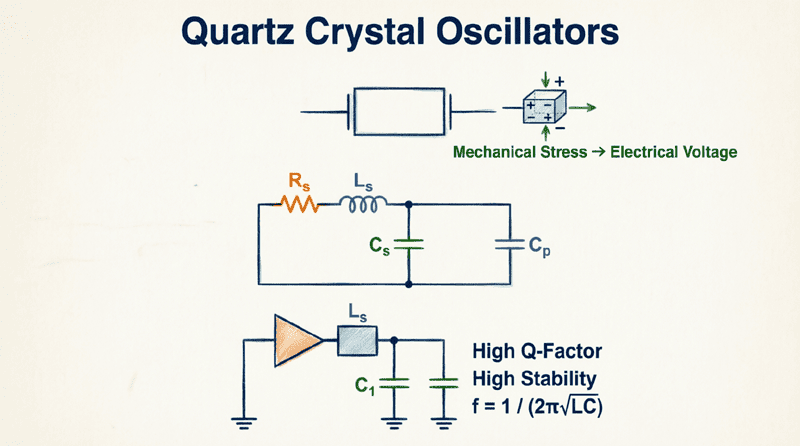
The Colpitts configuration is ideal for crystal oscillators because the crystal replaces the inductor in the tank circuit. The capacitive feedback network provides excellent stability, and the circuit naturally satisfies the phase requirements for crystal oscillation. This topology is used in Pierce and Clapp crystal oscillators.
Practical Design Example
Let’s design a Colpitts oscillator operating at 10 MHz using a 2N3904 NPN transistor.
Step 1: Define Specifications
- Target Frequency ($f_r$): 10 MHz
- Supply Voltage ($V_{CC}$): 12V
- Transistor: 2N3904 ($f_T \approx 300$ MHz, suitable for 10 MHz operation)
Step 2: Select the Inductor
Choose a practical inductor value. For 10 MHz, a value between 1 μH and 10 μH is typical. Let’s select:
$L = 2.2 \text{ \mu H}$
Step 3: Calculate Required Equivalent Capacitance
Rearrange the frequency formula to solve for $C_{eq}$:
$C_{eq} = \frac{1}{(2\pi f_r)^2 L}$
$C_{eq} = \frac{1}{(2\pi \times 10 \times 10^6)^2 \times 2.2 \times 10^{-6}}$
$C_{eq} = \frac{1}{(6.283 \times 10^7)^2 \times 2.2 \times 10^{-6}}$
$C_{eq} = \frac{1}{3.947 \times 10^{15} \times 2.2 \times 10^{-6}}$
$C_{eq} = \frac{1}{8.68 \times 10^9} = 115 \times 10^{-12}$
$C_{eq} \approx 115 \text{ pF}$
Step 4: Select $C_1$ and $C_2$
We need two capacitors in series that give 115 pF equivalent. A good starting ratio is $C_2 = 3 \times C_1$ to provide adequate feedback.
Using the series capacitance formula:
$C_{eq} = \frac{C_1 C_2}{C_1 + C_2}$
Substituting $C_2 = 3C_1$:
$115 = \frac{C_1 (3C_1)}{C_1 + 3C_1} = \frac{3C_1^2}{4C_1} = \frac{3C_1}{4}$
$C_1 = \frac{115 \times 4}{3} = 153 \text{ pF}$
$C_2 = 3 \times 153 = 459 \text{ pF}$
Use standard values:
- $C_1 = 150 \text{ pF}$
- $C_2 = 470 \text{ pF}$
Verify:
$C_{eq} = \frac{150 \times 470}{150 + 470} = \frac{70,500}{620} = 113.7 \text{ pF}$ ✓
Recalculate frequency:
$f_r = \frac{1}{2\pi\sqrt{2.2 \times 10^{-6} \times 113.7 \times 10^{-12}}}$
$f_r = 10.05 \text{ MHz}$ ✓
Step 5: Determine Required Gain
$A_v \geq \frac{C_2}{C_1} = \frac{470}{150} \approx 3.1$
The amplifier needs a voltage gain of at least 3.1. For a common-emitter amplifier, this is easily achievable.
Step 6: Bias Network Design
Design a standard voltage divider bias for the 2N3904:
- Target $I_C = 2 \text{ mA}$
- Target $V_{CE} = 6 \text{ V}$ (mid-supply)
- $R_C = 2.2 \text{ k}\Omega$
- $R_E = 1 \text{ k}\Omega$ (bypassed with a large capacitor for AC gain)
- $R_1 = 47 \text{ k}\Omega$
- $R_2 = 10 \text{ k}\Omega$
Add an RF choke or resistor in series with the collector to isolate the tank circuit from the DC supply.
Real-World Applications
1. Crystal Oscillators (Pierce Oscillator)
The most common application of the Colpitts topology is in crystal oscillators. When a quartz crystal replaces the inductor, the circuit becomes a Pierce oscillator, which is the standard configuration for microcontroller clocks, digital watches, and communication equipment. The crystal provides exceptional frequency stability (±10-100 ppm).
2. VHF/UHF Radio Transmitters
Colpitts oscillators are widely used in VHF (30-300 MHz) and UHF (300 MHz – 3 GHz) transmitters for:
- FM radio broadcasting
- Amateur radio (ham radio)
- Wireless microphones
- RFID systems
The topology’s excellent high-frequency performance and low harmonic content make it ideal for these applications.
3. Local Oscillators in Receivers
In superheterodyne receivers, the Colpitts oscillator serves as the local oscillator (LO) that mixes with incoming RF signals to produce the intermediate frequency (IF). Its stability ensures accurate tuning and minimal drift.
4. Signal Generators and Test Equipment
Laboratory RF signal generators often use Colpitts oscillators in their frequency synthesis sections. The clean output waveform reduces the need for extensive filtering.
5. Voltage-Controlled Oscillators (VCOs)
By replacing one of the capacitors (typically $C_2$) with a varactor diode (voltage-variable capacitor), the Colpitts oscillator becomes a VCO. This is essential for:
- Phase-locked loops (PLLs)
- Frequency modulation (FM)
- Frequency synthesizers
Comparison: Colpitts vs. Hartley
| Feature | Colpitts Oscillator | Hartley Oscillator |
|---|---|---|
| Feedback Network | Capacitive divider ($C_1$, $C_2$) | Inductive divider ($L_1$, $L_2$) |
| Frequency Stability | Excellent (better) | Good |
| Waveform Purity | Low distortion (better) | Moderate distortion |
| High-Frequency Performance | Excellent (VHF/UHF) | Good (HF/VHF) |
| Tuning Ease | Difficult (needs dual-gang cap) | Easy (single variable cap) |
| VFO Suitability | Poor | Excellent |
| Crystal Oscillator | Ideal (Pierce configuration) | Not suitable |
| Component Cost | Moderate (precision caps) | Low (inductors cheaper) |
Summary: Choose Colpitts for fixed-frequency, high-stability, high-frequency applications. Choose Hartley for variable-frequency (VFO) applications where tuning range is more important than spectral purity.
The Colpitts oscillator represents a pinnacle of LC oscillator design, offering superior performance in terms of frequency stability, waveform purity, and high-frequency operation. Its capacitive feedback topology, while slightly more complex to tune than the Hartley’s inductive approach, provides significant advantages that make it the preferred choice for precision RF applications.
Key Takeaways:
- Topology: Uses a capacitive voltage divider ($C_1$ and $C_2$) in series with a single inductor ($L$) to form the tank circuit.
- Frequency Formula: $f_r = \frac{1}{2\pi\sqrt{L C_{eq}}}$ where $C_{eq} = \frac{C_1 C_2}{C_1 + C_2}$
- Feedback and Gain: Feedback fraction $\beta \approx \frac{C_1}{C_2}$, requiring minimum gain $A_v \geq \frac{C_2}{C_1}$
- Phase Shift: 180° from the amplifier plus 180° from the capacitive divider equals 360° total, satisfying the Barkhausen criterion.
- Primary Advantages:
- Superior frequency stability
- Lower harmonic distortion
- Excellent VHF/UHF performance
- Ideal for crystal oscillators (Pierce configuration)
- Primary Disadvantages:
- Difficult to tune (requires variable inductor or dual-gang capacitor)
- Less suitable for VFO applications compared to Hartley
- Applications: Crystal oscillators, VHF/UHF transmitters, local oscillators, signal generators, and voltage-controlled oscillators (VCOs).
Mastering the Colpitts oscillator provides you with a powerful tool for RF design. Whether you’re building a precision clock circuit for a microcontroller, designing a low-distortion RF signal source, or creating a stable local oscillator for a receiver, the Colpitts topology offers the performance and reliability that modern electronics demand.