Twin-T Oscillator
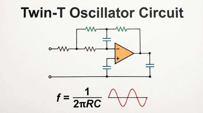
Twin-T Oscillator: Complete Guide to High-Selectivity RC Oscillators
Introduction to the Twin-T Oscillator
The Twin-T Oscillator represents a sophisticated evolution in RC oscillator design, offering superior frequency selectivity and stability compared to standard RC phase shift oscillators. Named for its distinctive topology featuring two “T” shaped RC networks connected in parallel, this circuit creates a highly selective notch filter that provides the precise phase shift and attenuation characteristics needed for stable oscillation.
While the Wien bridge oscillator dominates general-purpose audio applications, the Twin-T oscillator excels in situations requiring exceptional frequency stability and narrow bandwidth. Its unique twin-tee network creates a deep null at a specific frequency, making it ideal for applications where precise frequency control is paramount, such as in audio test equipment, tone generators, and specialized measurement circuits.
The Twin-T oscillator is particularly valued for its ability to produce very pure sine waves with minimal harmonic distortion. The high Q-factor of the twin-tee network (typically Q = 0.25 to 0.5 for passive versions, but much higher with active feedback) provides excellent frequency discrimination, ensuring that oscillations occur only at the desired frequency.
This comprehensive guide will explore the Twin-T oscillator’s unique topology, mathematical analysis, design procedures, and practical applications, demonstrating why this circuit remains a valuable tool in the analog designer’s arsenal.
What is a Twin-T Oscillator?
A Twin-T oscillator is an RC oscillator circuit that uses two T-shaped RC networks (one low-pass and one high-pass) connected in parallel to create a highly selective notch filter. At the resonant frequency, the network provides zero output (infinite attenuation) and 180° phase shift, which when combined with an inverting amplifier, produces stable oscillations with excellent frequency selectivity and low distortion.
Circuit Topology and Operation
The Twin-T Network Structure
The heart of the Twin-T oscillator is the twin-tee network, a passive RC filter consisting of two parallel T-shaped networks:
- Low-Pass T-Network:
- Two resistors ($R$) in series from input to output
- One capacitor ($2C$) from the junction of the resistors to ground
- This network passes low frequencies and attenuates high frequencies
- High-Pass T-Network:
- Two capacitors ($C$) in series from input to output
- One resistor ($R/2$) from the junction of the capacitors to ground
- This network passes high frequencies and attenuates low frequencies
When these two networks are connected in parallel, they create a band-reject (notch) filter. At most frequencies, the signals from the two paths cancel each other out due to phase differences. However, at one specific frequency—the notch frequency—the cancellation is complete, resulting in zero output.
Oscillation Principle
The Twin-T oscillator operates on a clever principle:
- At the Notch Frequency: The twin-tee network provides infinite attenuation (theoretically) and exactly 180° phase shift.
- Amplifier Feedback: An inverting amplifier (providing another 180° phase shift) is connected around the twin-tee network.
- Total Phase Shift: 180° (twin-tee) + 180° (amplifier) = 360° (or 0°), satisfying the Barkhausen criterion for positive feedback.
- Gain Requirement: At the notch frequency, the twin-tee network has zero transmission. To sustain oscillations, the amplifier must provide sufficient gain to overcome this, which is achieved by adding a small amount of positive feedback or by operating slightly off the exact notch frequency where there is finite attenuation.
In practice, the circuit is designed to oscillate at a frequency very close to, but not exactly at, the notch frequency, where the attenuation is very high but finite, and the phase shift is very close to 180°.
How does the Twin-T network create oscillation?
The twin-tee network acts as a notch filter with 180° phase shift at the notch frequency. When placed in the feedback loop of an inverting amplifier (which adds another 180° phase shift), the total loop phase shift becomes 360°, creating positive feedback. The circuit oscillates at the frequency where the loop gain equals unity.
Mathematical Analysis of the Twin-T Oscillator
Notch Frequency Calculation
For a balanced Twin-T network where the component values satisfy the relationships:
- $R_1 = R_2 = R$
- $R_3 = R/2$
- $C_1 = C_2 = C$
- $C_3 = 2C$
The notch frequency ($f_n$) is given by:
$f_n = \frac{1}{2\pi R C}$
Where:
- $f_n$ = Notch frequency in Hertz (Hz)
- $R$ = Resistance in Ohms ($\Omega$)
- $C$ = Capacitance in Farads (F)
This formula is identical to the Wien bridge oscillator’s frequency formula, but the Twin-T network’s behavior is fundamentally different—it creates a notch (minimum) rather than a peak (maximum) at this frequency.
Transfer Function and Q-Factor
The transfer function of the Twin-T network is complex, but at frequencies near the notch, it can be approximated. The Q-factor of a passive Twin-T network is inherently low:
$Q_{passive} = 0.25$
This low Q means the notch is relatively broad. However, by adding positive feedback (regeneration), the effective Q can be dramatically increased, sharpening the notch and improving frequency selectivity.
With active feedback, the effective Q becomes:
$Q_{active} = \frac{Q_{passive}}{1 – K}$
Where $K$ is the feedback factor (0 < K < 1). As K approaches 1, Q approaches infinity, creating an extremely sharp notch.
Gain Requirement
For oscillation to occur, the amplifier must provide sufficient gain to compensate for the attenuation of the Twin-T network at the oscillation frequency. The minimum gain required depends on how close the oscillation frequency is to the exact notch frequency.
In a typical design with positive feedback to increase Q, the gain is set slightly higher than the theoretical minimum to ensure reliable startup, then amplitude stabilization circuits limit the output to prevent distortion.
Practical Design Example: 1 kHz Twin-T Oscillator
Let’s design a practical Twin-T oscillator operating at 1 kHz using a dual Op-Amp (one for the main amplifier, one for buffering/feedback control).
Step 1: Define Specifications
- Target Frequency ($f_n$): 1000 Hz (1 kHz)
- Supply Voltage: $\pm 12V$ (Dual supply for the Op-Amps)
- Active Device: TL072 dual Op-Amp (Low noise, JFET-input)
- Target Q: High (using positive feedback)
Step 2: Select the Capacitor
Choose a stable capacitor value. For 1 kHz, nanofarad range capacitors are practical.
$C = 10 \text{ nF}$ ($10 \times 10^{-9}$ F)
Step 3: Calculate the Resistor Value
Rearrange the notch frequency formula to solve for $R$:
$R = \frac{1}{2\pi f_n C}$
$R = \frac{1}{2\pi \times 1000 \times 10 \times 10^{-9}}$
$R = \frac{1}{6.283 \times 10^{-5}}$
$R \approx 15,915 \text{ } \Omega$
Use standard value: $R = 16 \text{ k}\Omega$
Step 4: Determine Twin-T Component Values
Low-Pass T:
- $R_1 = R_2 = 16 \text{ k}\Omega$
- $C_3 = 2C = 20 \text{ nF}$ (use two 10 nF in parallel, or one 22 nF)
High-Pass T:
- $C_1 = C_2 = 10 \text{ nF}$
- $R_3 = R/2 = 8 \text{ k}\Omega$ (use 8.2 kΩ standard value)
Step 5: Design the Amplifier
Use a non-inverting Op-Amp configuration for the main amplifier. The gain must be sufficient to overcome the Twin-T attenuation.
For a Twin-T oscillator with positive feedback, a typical gain is:
$A_v = 3$ to $10$
Let’s choose $A_v = 5$ for reliable startup.
For a non-inverting amplifier:
$A_v = 1 + \frac{R_f}{R_g} = 5$
Therefore: $\frac{R_f}{R_g} = 4$
Choose $R_g = 10 \text{ k}\Omega$
Then $R_f = 40 \text{ k}\Omega$ (use 39 kΩ standard value)
Step 6: Add Positive Feedback for Q-Enhancement
To increase the Q-factor and sharpen the notch, add a voltage divider from the output back to the junction of the Twin-T network (the ground point of the low-pass T and high-pass T).
Use a potentiometer (e.g., 10 kΩ) to adjust the feedback level. This allows fine-tuning of the Q and ensures reliable oscillation startup.
Step 7: Amplitude Stabilization
As with other oscillators, amplitude stabilization is needed. Use back-to-back diodes (1N4148) in parallel with a portion of $R_f$, or implement a JFET-based AGC circuit for lower distortion.
Advantages and Disadvantages
Advantages
- Excellent Frequency Selectivity: The Twin-T network provides very sharp frequency discrimination, especially with Q-enhancement. This makes it ideal for applications requiring precise frequency control.
- Low Distortion: When properly designed with amplitude stabilization, the Twin-T oscillator can produce very clean sine waves with low harmonic distortion (< 0.1%).
- Good Frequency Stability: The passive RC network is relatively stable with temperature, and the high Q makes the frequency less sensitive to component variations.
- Simple Component Values: The component values are straightforward to calculate and implement, with standard resistor and capacitor values.
- Adjustable Frequency: By using a dual-gang potentiometer for the resistors (or capacitors), the frequency can be tuned over a limited range.
Disadvantages
- Component Matching Critical: The Twin-T network requires precise component matching for optimal performance. The ratios $R_1 = R_2 = 2R_3$ and $C_1 = C_2 = C_3/2$ must be maintained for a deep notch.
- Limited Tuning Range: Unlike the Wien bridge oscillator, the Twin-T has a more limited tuning range when using variable components, because changing component values affects the balance of the network.
- Complex Feedback Network: The need for both negative feedback (for gain control) and positive feedback (for Q-enhancement) makes the circuit more complex than simpler RC oscillators.
- Startup Reliability: Without careful design, the circuit may fail to start oscillating, especially if the Q is set too high or the gain is marginal.
- Sensitivity to Component Tolerances: Frequency accuracy depends heavily on component precision. High-stability applications require 1% or better tolerance components.
Why is component matching critical in a Twin-T oscillator?
The Twin-T network relies on precise cancellation between its low-pass and high-pass branches to create the notch. If the component ratios ($R_1 = R_2 = 2R_3$ and $C_1 = C_2 = C_3/2$) are not maintained, the notch becomes shallow, phase shift deviates from 180°, and the oscillator may fail to work or produce distorted output.
Real-World Applications
1. Audio Test Equipment
Twin-T oscillators are used in audio signal generators where precise frequency control and low distortion are required. They are particularly useful for measuring frequency response, distortion, and other audio parameters.
2. Tone Generators
In musical instruments, alarms, and signaling devices, the Twin-T oscillator provides stable, pure tones at specific frequencies.
3. Notch Filters
The Twin-T network itself (without the oscillator feedback) is widely used as a notch filter to eliminate specific interference frequencies, such as 50 Hz or 60 Hz power line hum in audio and measurement systems.
4. Educational Demonstrations
The Twin-T oscillator is a popular circuit in university electronics laboratories, teaching students about:
- Filter design
- Feedback theory
- Oscillator principles
- Component matching and tolerance effects
5. Precision Signal Sources
In applications requiring a stable, low-frequency reference signal, the Twin-T oscillator provides better performance than simple RC phase shift oscillators.
Comparison: Twin-T vs. Wien Bridge vs. RC Phase Shift
| Feature | Twin-T Oscillator | Wien Bridge Oscillator | RC Phase Shift Oscillator |
|---|---|---|---|
| Frequency Selectivity | Excellent (High Q) | Good | Fair |
| Distortion | Low (< 0.1%) | Very Low (< 0.05%) | Moderate (1-5%) |
| Component Matching | Critical | Moderate | Not critical |
| Circuit Complexity | High | Moderate | Low |
| Tuning Range | Limited | Wide | Moderate |
| Startup Reliability | Moderate | Good | Good |
| Applications | Precision audio, notch filters | General audio test | Simple tone generation |
Summary: Choose the Twin-T for applications requiring high frequency selectivity and precise frequency control. Choose the Wien bridge for general-purpose low-distortion audio generation. Choose the RC phase shift for simple, low-cost oscillators.
The Twin-T oscillator represents a sophisticated approach to RC oscillator design, offering superior frequency selectivity and stability through its unique twin-tee network topology. While more complex than simpler RC oscillators, its ability to produce clean, stable sine waves at precise frequencies makes it invaluable for demanding audio and measurement applications.
Key Takeaways:
- Topology: Uses two parallel T-networks (one low-pass, one high-pass) to create a highly selective notch filter with 180° phase shift at the notch frequency.
- Frequency Formula: $f_n = \frac{1}{2\pi R C}$ for a balanced network.
- Component Relationships: Critical matching required: $R_1 = R_2 = 2R_3$ and $C_1 = C_2 = C_3/2$.
- Q-Enhancement: Positive feedback can dramatically increase the effective Q, sharpening the notch and improving frequency stability.
- Primary Advantages:
- Excellent frequency selectivity
- Low distortion
- Good frequency stability
- Precise frequency control
- Primary Disadvantages:
- Critical component matching required
- Limited tuning range
- More complex circuit
- Sensitivity to component tolerances
- Applications: Audio test equipment, precision tone generators, notch filters, and educational demonstrations.
The Twin-T oscillator remains a valuable circuit for engineers requiring precise, stable, low-frequency signal generation. Its unique combination of high selectivity and low distortion ensures its continued relevance in modern analog design.