The RC Oscillator Circuit
The RC Oscillator Circuit: Complete Guide to Phase Shift and Audio Oscillators
Introduction to RC Oscillators
While LC oscillators dominate the radio frequency (RF) spectrum, a different class of circuits takes over when we need to generate signals at lower frequencies. Enter the RC Oscillator. By replacing bulky and expensive inductors with simple resistors (R) and capacitors (C), RC oscillators provide a practical, compact, and cost-effective solution for generating audio and sub-audio frequencies (typically from a few Hertz up to about 1 MHz).
RC oscillators are the workhorses of audio engineering, test equipment, and low-frequency signal generation. Whether you are listening to a synthesized musical tone, testing an audio amplifier with a function generator, or reading data from a low-frequency sensor, an RC oscillator is likely generating the underlying signal.
Unlike LC tank circuits that rely on the physical exchange of energy between magnetic and electric fields, RC oscillators rely on frequency-dependent phase shifting and attenuation networks to satisfy the conditions for oscillation.
This comprehensive guide will explore the fundamental principles of RC oscillator circuits, focusing heavily on the foundational RC Phase Shift Oscillator. We will dissect its topology, mathematical analysis, design procedures, and practical applications, setting the stage for more advanced RC topologies like the Wien Bridge and Twin-T oscillators.
What is an RC Oscillator?
An RC oscillator is an electronic circuit that uses a network of resistors and capacitors to determine its frequency of oscillation. Instead of an LC tank circuit, it uses RC phase-shift networks to provide the necessary 180-degree phase shift and frequency selectivity, making it ideal for generating audio and low-frequency signals without the need for bulky inductors.
The Physics of RC Networks
To understand how an RC oscillator works, we must first understand how a simple RC circuit affects an AC signal.
Phase Shift in a Single RC Network
When an AC signal passes through a simple RC circuit (either a high-pass or low-pass filter), two things happen:
- Attenuation: The amplitude of the signal is reduced.
- Phase Shift: The phase of the output signal is shifted relative to the input.
For a single RC stage, the maximum theoretical phase shift is 90 degrees. However, at exactly 90 degrees, the output amplitude is zero, which is useless for an oscillator. In practical oscillator design, a single RC stage is typically designed to provide a phase shift of 60 degrees. At 60 degrees, the signal is still attenuated, but it retains enough amplitude to be useful.
The RC Ladder Network
Since a single RC stage can only provide up to 60 degrees of practical phase shift, we need multiple stages to achieve the 180 degrees required for oscillation (when combined with an inverting amplifier).
By cascading three identical RC stages (an RC ladder network), we achieve:
$60^\circ + 60^\circ + 60^\circ = 180^\circ$ total phase shift.
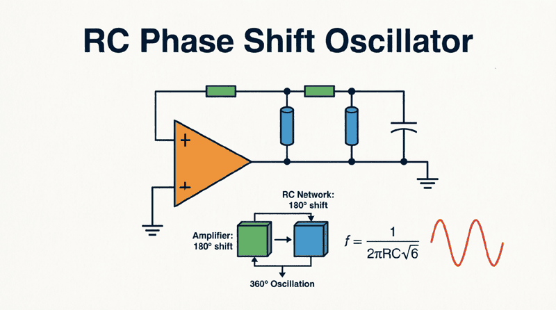
This 3-stage RC ladder is the heart of the classic RC Phase Shift Oscillator. At one specific frequency, this network will provide exactly 180 degrees of phase shift. If we feed this output back to an inverting amplifier (which provides another 180 degrees), the total loop phase shift becomes 360 degrees (or 0 degrees), satisfying the Barkhausen criterion for positive feedback.
Why do RC phase shift oscillators use three RC stages?
A single RC network can practically provide a maximum of 60 degrees of phase shift without completely attenuating the signal. By cascading three RC stages, the circuit achieves the 180 degrees of phase shift required to combine with the 180-degree phase shift of an inverting amplifier, creating the 360-degree total loop shift needed for oscillation.
The RC Phase Shift Oscillator: Topology and Operation
Circuit Configuration
The classic RC Phase Shift Oscillator consists of two main blocks:
- The Inverting Amplifier: This can be a BJT transistor in a common-emitter configuration, a FET in a common-source configuration, or an Operational Amplifier (Op-Amp) in an inverting configuration. The amplifier provides the necessary voltage gain and the initial 180-degree phase shift.
- The Feedback Network: This is the 3-stage RC ladder network. The output of the amplifier is fed into the first RC stage, the output of the first stage feeds the second, and the output of the second feeds the third. The output of the third stage is fed back to the input of the amplifier.
Satisfying the Barkhausen Criterion
For sustained oscillations, the circuit must meet two conditions:
1. Phase Condition:
The amplifier provides $180^\circ$. The 3-stage RC network provides $180^\circ$ at the resonant frequency. Total phase shift = $360^\circ$ (or $0^\circ$). Condition met.
2. Amplitude (Gain) Condition:
The 3-stage RC network heavily attenuates the signal. In fact, at the frequency where the phase shift is exactly 180 degrees, the network attenuates the signal by a factor of exactly 1/29.
Therefore, to maintain a loop gain of exactly 1 ($A_v \times \beta = 1$), the amplifier must provide a gain ($A_v$) of at least 29 to overcome this attenuation. If the gain is less than 29, oscillations will die out. If it is significantly greater than 29, the output will clip and distort.
Mathematical Analysis
Frequency of Oscillation
For a standard RC phase shift oscillator using three identical RC stages (where $R_1=R_2=R_3=R$ and $C_1=C_2=C_3=C$), the frequency of oscillation ($f_r$) is given by:
$f_r = \frac{1}{2\pi R C \sqrt{6}}$
Where:
- $f_r$ = Frequency of oscillation in Hertz (Hz)
- $R$ = Resistance in Ohms ($\Omega$)
- $C$ = Capacitance in Farads (F)
- $\sqrt{6}$ $\approx 2.449$
(Note: If the RC network is loaded by the amplifier’s input impedance, the formula becomes slightly more complex, but this is the standard approximation for high-impedance Op-Amp designs).
Minimum Gain Requirement
As established, the attenuation of the 3-stage RC network is 1/29. Therefore, the minimum voltage gain required from the amplifier is:
$A_v \geq 29$
For an inverting Op-Amp configuration, the gain is set by the feedback resistor ($R_f$) and the input resistor ($R_{in}$):
$A_v = \frac{R_f}{R_{in}} \geq 29$
This means $R_f$ must be at least 29 times larger than $R_{in}$.
Advantages and Disadvantages
Advantages
- No Inductors: The most significant advantage is the elimination of bulky, heavy, and expensive inductors. This makes RC oscillators ideal for integrated circuits (ICs) and compact PCB designs.
- Excellent for Audio Frequencies: They are perfectly suited for the 20 Hz to 20 kHz audio range, where LC oscillators would require impractically large inductors and capacitors.
- Good Frequency Tuning: By using a multi-gang variable resistor (potentiometer) in place of the fixed resistors in the RC network, the frequency can be tuned smoothly over a wide range.
- Clean Output (with stabilization): When properly designed with amplitude stabilization, they can produce very low-distortion sine waves.
Disadvantages
- Limited High-Frequency Performance: Due to the parasitic capacitances of the active devices and the RC time constants, RC oscillators are generally limited to frequencies below 1 MHz.
- Poor Frequency Stability: Compared to LC or crystal oscillators, the frequency of an RC oscillator is more susceptible to temperature variations and component aging.
- High Gain Requirement: The amplifier must provide a relatively high gain (at least 29) just to overcome the losses in the feedback network, which can sometimes lead to stability issues or noise amplification.
What is the minimum gain required for an RC phase shift oscillator?
The minimum voltage gain required for an RC phase shift oscillator is 29. This is because the three-stage RC feedback network attenuates the signal by a factor of 1/29 at the resonant frequency. The amplifier must provide a gain of at least 29 to sustain oscillations.
Practical Design Example: 1 kHz Op-Amp Oscillator
Let’s design a practical RC phase shift oscillator operating at 1 kHz using a standard LM741 or TL071 Operational Amplifier.
Step 1: Define Specifications
- Target Frequency ($f_r$): 1000 Hz (1 kHz)
- Supply Voltage: $\pm 12V$ (Dual supply for the Op-Amp)
- Active Device: TL071 Op-Amp (Low noise, good for audio)
Step 2: Select the Capacitor
Choose a standard, stable capacitor value for the RC network. For audio frequencies, ceramic or film capacitors in the nanofarad range are ideal.
$C = 10 \text{ nF}$ ($10 \times 10^{-9}$ F)
Step 3: Calculate the Resistor Value
Rearrange the frequency formula to solve for $R$:
$R = \frac{1}{2\pi f_r C \sqrt{6}}$
$R = \frac{1}{2\pi \times 1000 \times 10 \times 10^{-9} \times 2.449}$
$R = \frac{1}{6.283 \times 10^{-5} \times 2.449}$
$R = \frac{1}{0.0001538} \approx 6500 \text{ } \Omega$
Use standard value: $R = 6.8 \text{ k}\Omega$
(Recalculating exact frequency with 6.8k: $f = 1 / (2\pi \times 6800 \times 10n \times 2.449) = 953 \text{ Hz}$. Close enough for audio applications, or use a 6.5k trimmer potentiometer for exact 1 kHz tuning).
Step 4: Design the Amplifier Gain
We need a gain of at least 29. Let’s choose an input resistor ($R_{in}$) and calculate the feedback resistor ($R_f$).
Let $R_{in} = 10 \text{ k}\Omega$
$R_f = 29 \times R_{in} = 29 \times 10 \text{ k}\Omega = 290 \text{ k}\Omega$
To allow for slight component tolerances and ensure startup, we can make the gain slightly higher, say 32.
$R_f = 320 \text{ k}\Omega$ (or use a $270 \text{ k}\Omega$ fixed resistor in series with a $50 \text{ k}\Omega$ trimmer).
Step 5: Circuit Assembly
- Connect the three 6.8k resistors and three 10nF capacitors in a ladder network from the Op-Amp output to the inverting input (-).
- Connect $R_{in}$ (10k) from the last capacitor to the inverting input (-).
- Connect $R_f$ (320k) from the output to the inverting input (-).
- Connect the non-inverting input (+) to ground.
- Apply $\pm 12V$ to the power pins.
Amplitude Stabilization
In the design above, if the gain is set to exactly 29, oscillations might not start due to component tolerances. If the gain is set to 35 or 40 to guarantee startup, the output sine wave will quickly grow until it hits the power supply rails ($\pm 12V$), resulting in a heavily clipped, square-like wave rich in harmonics.
To get a pure sine wave, the gain must automatically adjust to exactly 29 once the oscillations reach the desired amplitude. This is called Amplitude Stabilization or Automatic Gain Control (AGC).
Common Stabilization Techniques:
- Back-to-Back Diodes: Placing two small signal diodes (e.g., 1N4148) in parallel with a portion of the feedback resistor ($R_f$). At low amplitudes, the diodes are off, and the gain is high (e.g., 40). As the amplitude increases and reaches the diode forward voltage (~0.7V), the diodes conduct, effectively lowering the resistance of $R_f$ and reducing the gain to exactly 29.
- JFET as a Voltage-Variable Resistor: A JFET is placed in the feedback path. The output amplitude is rectified and filtered to create a DC control voltage that biases the JFET, smoothly adjusting its resistance to maintain a constant output amplitude.
- Incandescent Lamp (Classic Method): In older designs (like the classic HP 200A audio oscillator), a tiny incandescent bulb is used as $R_{in}$. As the output amplitude increases, the bulb heats up, its resistance increases, and the gain ($R_f / R_{in}$) decreases, naturally stabilizing the amplitude.
Real-World Applications
1. Audio Tone Generators
RC phase shift oscillators are widely used in musical instruments, alarms, and beepers to generate specific audio tones. Their ability to operate cleanly in the 20 Hz – 20 kHz range makes them perfect for this.
2. Function Generators
Bench-top function generators use RC oscillator topologies (often Wien Bridge, which is a variation) to produce sine, square, and triangle waves for testing audio amplifiers, filters, and speakers.
3. Low-Frequency Signal Sources
In scientific and industrial applications, RC oscillators are used to generate low-frequency control signals, clock pulses for slow digital logic, and test signals for sensor calibration.
4. Modulation Circuits
Because the frequency of an RC oscillator can be easily changed by varying a resistor (e.g., using a JFET as a voltage-controlled resistor), they are frequently used as Voltage-Controlled Oscillators (VCOs) in low-frequency Frequency Modulation (FM) circuits.
The RC oscillator circuit, particularly the RC Phase Shift topology, is a fundamental building block in low-frequency electronics. By cleverly utilizing the phase-shifting properties of resistors and capacitors, it eliminates the need for inductors, offering a compact and cost-effective solution for audio and sub-audio signal generation.
Key Takeaways:
- Core Principle: Uses a 3-stage RC ladder network to provide 180 degrees of phase shift, combining with an inverting amplifier’s 180 degrees to satisfy the Barkhausen criterion.
- Frequency Formula: $f_r = \frac{1}{2\pi R C \sqrt{6}}$ for identical RC stages.
- Gain Requirement: The feedback network attenuates the signal by 1/29, requiring the amplifier to have a minimum voltage gain of 29.
- Advantages: No inductors, excellent for audio frequencies, easy to tune with variable resistors.
- Disadvantages: Limited to < 1 MHz, lower frequency stability than LC/crystal oscillators.
- Amplitude Control: Essential for preventing waveform clipping; typically achieved using diodes, JFETs, or thermal resistors in the feedback loop.
Mastering the RC phase shift oscillator provides a solid foundation for understanding more advanced RC topologies. In the following articles, we will explore the Wien Bridge Oscillator, which improves upon this design for better audio performance, and the Twin-T Oscillator, which offers superior frequency selectivity.