Asynchronous Counter
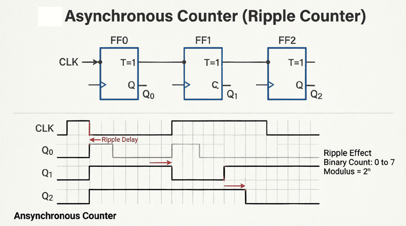
Asynchronous Counter (Ripple Counter): Complete Guide to Design & Operation
Introduction to Asynchronous Counters
Counters are sequential logic circuits used to count clock pulses, divide frequencies, and manage timing operations. Among the various types of counters, the Asynchronous Counter, commonly known as a Ripple Counter, is one of the most fundamental and widely taught circuits.
Unlike synchronous counters where all flip-flops share a common clock signal, an asynchronous counter is characterized by its cascaded clocking mechanism. The output of one flip-flop serves as the clock input for the next flip-flop in the chain. This creates a “ripple” effect as the clock pulse propagates through the circuit, hence the name “Ripple Counter.”
Asynchronous counters are highly valued for their simplicity and minimal component requirements. They are frequently used in basic frequency division, digital clocks, and event counting applications where ultra-high-speed operation is not a strict requirement.
This comprehensive guide will explore the inner workings of asynchronous counters, detailing their design, operation, timing characteristics, and the critical concept of propagation delay. We will also examine how to configure them for up-counting and down-counting, and discuss their practical applications in modern digital systems.
What is an Asynchronous (Ripple) Counter?
An asynchronous counter, or ripple counter, is a digital sequential circuit where flip-flops are connected in a cascade. The external clock signal drives only the first flip-flop, and the output of each flip-flop clocks the subsequent one. This causes the clock signal to “ripple” through the circuit, resulting in a slight delay between the state changes of the individual flip-flops.
How Asynchronous Counters Work
The Cascading Flip-Flop Mechanism
The core building block of an asynchronous counter is the T flip-flop (Toggle flip-flop) or a JK flip-flop configured in toggle mode. In toggle mode, the J and K inputs of a JK flip-flop are tied to logic HIGH (1). Every time a clock pulse is applied, the output (Q) toggles to its opposite state.
In an asynchronous counter, these flip-flops are connected in a series chain:
- The external clock signal is connected to the clock input (CLK) of the first flip-flop (FF0).
- The output (Q) of FF0 is connected to the clock input of the second flip-flop (FF1).
- The output (Q) of FF1 is connected to the clock input of the third flip-flop (FF2), and so on.
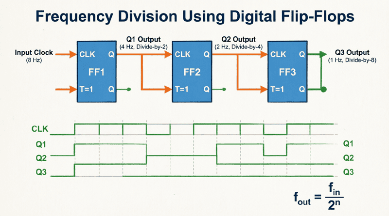
Because each flip-flop divides the frequency of its input clock by 2, the first flip-flop divides the external clock by 2, the second divides it by 4, the third by 8, and the n-th flip-flop divides it by $2^n$.
The “Ripple” Effect
The term “ripple” perfectly describes the behavior of this circuit. When a clock pulse arrives at the first flip-flop, it changes state almost immediately. However, this change in state is what triggers the second flip-flop. The second flip-flop then changes state, which triggers the third, and so on.
The clock signal effectively “ripples” through the chain of flip-flops. Because each flip-flop takes a tiny amount of time to react to its clock input (known as propagation delay), the final output of the counter does not change instantaneously with the external clock. Instead, the state change ripples from the Least Significant Bit (LSB) to the Most Significant Bit (MSB).
Why is it called a Ripple Counter?
It is called a ripple counter because the clock signal does not reach all flip-flops simultaneously. Instead, the output of one flip-flop triggers the next, causing the state change to “ripple” sequentially through the chain from the LSB to the MSB.
Designing Asynchronous Up and Down Counters
Asynchronous counters can be easily configured to count upwards (increment) or downwards (decrement) by simply changing how the flip-flops are interconnected.
Asynchronous Up Counter
In an Asynchronous Up Counter, the counter increments its binary value with each incoming clock pulse (e.g., 000, 001, 010, 011, 100…).
Design Rule for Up Counters:
To create an up counter using negative-edge-triggered flip-flops (which trigger on the falling edge of the clock), the non-inverted output (Q) of the preceding flip-flop is connected to the clock input of the next flip-flop.
Why this works: When a flip-flop toggles from 1 to 0 (a falling edge), it triggers the next flip-flop to toggle. This perfectly mimics binary addition, where a carry is generated when a bit rolls over from 1 to 0.
Example: 3-Bit Asynchronous Up Counter
- FF0 (LSB): Toggled by the external clock. Output $Q_0$ represents $2^0$.
- FF1: Toggled by $Q_0$. Output $Q_1$ represents $2^1$.
- FF2 (MSB): Toggled by $Q_1$. Output $Q_2$ represents $2^2$.
- Count Sequence: 000 to 111 (0 to 7 in decimal), then resets to 000. This is a MOD-8 counter.
Asynchronous Down Counter
In an Asynchronous Down Counter, the counter decrements its binary value with each clock pulse (e.g., 111, 110, 101, 100, 011…).
Design Rule for Down Counters:
To create a down counter using negative-edge-triggered flip-flops, the inverted output ($\overline{Q}$) of the preceding flip-flop is connected to the clock input of the next flip-flop.
Why this works: A flip-flop’s inverted output ($\overline{Q}$) produces a falling edge when the normal output (Q) produces a rising edge (toggling from 0 to 1). In binary subtraction, a “borrow” occurs when a bit transitions from 0 to 1. By clocking the next stage with $\overline{Q}$, we trigger the next flip-flop exactly when a borrow is needed.
Asynchronous Up/Down Counter
By combining both the Q and $\overline{Q}$ outputs with logic gates (usually AND/OR gates or multiplexers), you can create a bidirectional counter. A control line (often labeled UP/DOWN) selects whether the Q outputs or the $\overline{Q}$ outputs are routed to the clock inputs of the subsequent flip-flops, allowing the counter to count up or down on the fly.
Propagation Delay and Maximum Frequency
The most significant limitation of asynchronous counters is propagation delay. Understanding this concept is crucial for designing reliable digital systems.
Understanding Propagation Delay ($t_{pd}$)
Every digital logic gate and flip-flop takes a finite amount of time to react to a change at its input and produce a stable change at its output. This time is called the propagation delay ($t_{pd}$). For standard TTL or CMOS flip-flops, this delay is typically in the range of 10 to 50 nanoseconds.
In a synchronous counter, all flip-flops are triggered by the same clock edge, so the total delay is just the delay of one flip-flop. However, in an asynchronous counter, the flip-flops are triggered sequentially.
Calculating Total Propagation Delay
The total propagation delay ($t_{pd(total)}$) of an asynchronous counter is the sum of the propagation delays of all the individual flip-flops in the chain:
$t_{pd(total)} = n \times t_{pd}$
Where:
- $n$ = Number of flip-flops in the counter
- $t_{pd}$ = Propagation delay of a single flip-flop
Example Calculation:
If a 4-bit asynchronous counter uses flip-flops with a propagation delay of 20 ns:
$t_{pd(total)} = 4 \times 20\text{ ns} = 80\text{ ns}$
This means it takes 80 nanoseconds for the counter to fully settle into its new state after a clock pulse is applied.
Maximum Clock Frequency ($f_{max}$)
Because the counter needs time to settle before the next clock pulse arrives, the propagation delay strictly limits the maximum operating frequency of the counter. The minimum clock period ($T_{min}$) must be greater than or equal to the total propagation delay:
$T_{min} \ge t_{pd(total)}$
Therefore, the maximum clock frequency is:
$f_{max} \le \frac{1}{t_{pd(total)}}$
Using the previous example ($t_{pd(total)} = 80\text{ ns}$):
$f_{max} = \frac{1}{80 \times 10^{-9}} = 12.5\text{ MHz}$
If you apply a clock signal faster than 12.5 MHz to this specific 4-bit counter, the flip-flops will not have enough time to settle, leading to incorrect counting and erratic behavior. This frequency limitation is the primary reason synchronous counters are preferred in high-speed digital systems.
How do you calculate the maximum frequency of an asynchronous counter?
The maximum frequency ($f_{max}$) is calculated by taking the reciprocal of the total propagation delay. First, multiply the number of flip-flops ($n$) by the propagation delay of a single flip-flop ($t_{pd}$) to get the total delay. Then, $f_{max} = 1 / (n \times t_{pd})$.
Decoding Glitches in Asynchronous Counters
Another critical issue associated with asynchronous counters is the occurrence of decoding glitches (also known as strobing errors or race conditions).
What are Decoding Glitches?
When an asynchronous counter transitions from one state to another, the flip-flops do not change state simultaneously due to the ripple effect. For a brief moment, the counter passes through intermediate, unintended states before settling on the final correct state.
Example of a Glitch:
Consider a 3-bit counter transitioning from state 011 (3) to 100 (4).
- The LSB (FF0) toggles from 1 to 0.
- This triggers FF1 to toggle from 1 to 0.
- This triggers FF2 to toggle from 0 to 1.
During this 80 ns ripple period, the counter briefly passes through the states 010 (2) and 000 (0) before finally settling at 100 (4).
If you are using combinational logic (like an AND gate) to decode a specific state—for example, to trigger an alarm when the count reaches 010—the decoder will momentarily see 010 during the transition from 3 to 4. This causes a false, momentary output pulse known as a glitch.
Eliminating Decoding Glitches
To prevent glitches from affecting downstream circuits, designers use a technique called strobe or enable gating.
Instead of letting the decoded output go directly to the next stage, the decoded output is ANDed with the main clock signal. The decoder is only allowed to output a signal when the clock is in a specific state (usually when the clock is LOW), which occurs after all the flip-flops have had time to settle and the ripple effect has completely finished.
Practical Applications of Asynchronous Counters
Despite their speed limitations, asynchronous counters are widely used in applications where high speed is not the primary concern, but simplicity and cost-effectiveness are.
1. Frequency Division
As discussed in the previous article, asynchronous counters are excellent frequency dividers. A 4-bit counter divides the input frequency by 16. By tapping the output of each individual flip-flop, you can extract multiple divided frequencies (divide-by-2, divide-by-4, divide-by-8, etc.) from a single master clock.
2. Digital Clocks and Timers
In digital clocks, a 32.768 kHz crystal oscillator is fed into a series of asynchronous counters (specifically, divide-by-2 stages) to eventually produce a precise 1 Hz (1 pulse per second) signal to drive the seconds display. The slight propagation delays are entirely negligible at these low audio frequencies.
3. Event Counting
Asynchronous counters are frequently used to count external events, such as products passing on a conveyor belt, people entering a room, or rotations of a motor shaft. Because the external events occur relatively slowly compared to the propagation delay of the flip-flops, the ripple effect does not cause any issues.
4. Non-Binary (MOD) Counters
While a standard n-bit asynchronous counter has a modulus (MOD) of $2^n$ (e.g., MOD-4, MOD-8, MOD-16), you can easily create custom MOD counters by adding a simple reset circuit.
For example, to create a MOD-6 counter (which counts from 0 to 5 and resets):
- Use a 3-bit counter (which naturally counts to 7).
- Use an AND gate to detect the binary state
110(decimal 6). - Connect the output of the AND gate to the asynchronous CLEAR (RESET) pins of all the flip-flops.
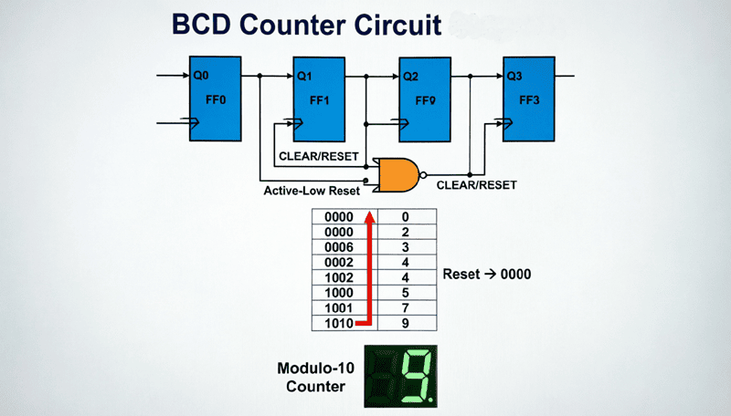
- As soon as the counter hits 6, it is instantly reset to 0, effectively skipping states 6 and 7 and creating a MOD-6 sequence.
Advantages and Disadvantages Summary
Advantages
- Simple Design: Requires minimal wiring and logic gates.
- Low Component Count: Uses fewer ICs compared to synchronous counters.
- Easy to Implement: Ideal for beginners and basic educational projects.
- Cost-Effective: Cheaper to manufacture for low-speed applications.
Disadvantages
- Propagation Delay: The cumulative delay limits the maximum operating frequency.
- Decoding Glitches: Intermediate states can cause false triggers in decoded outputs.
- Ripple Effect: Not suitable for applications requiring simultaneous state changes.
- Power Consumption: Can consume slightly more transient power during the ripple transition due to multiple gates switching in rapid succession.
The asynchronous (ripple) counter is a cornerstone of digital electronics education and a highly practical circuit for low-to-medium speed applications. By cascading toggle flip-flops, it elegantly performs binary counting and frequency division with minimal hardware.
However, the inherent “ripple” effect introduces propagation delays and decoding glitches, which strictly limit its maximum operating frequency and reliability in high-speed systems. Understanding these limitations is just as important as understanding how the counter works, as it dictates when to use an asynchronous counter versus a synchronous counter.
Key takeaways from this guide include:
- Operation: Flip-flops are cascaded, with the output of one clocking the next.
- Direction: Connecting Q to the next CLK creates an Up counter; connecting $\overline{Q}$ creates a Down counter.
- Timing: Total propagation delay is $n \times t_{pd}$, which dictates the maximum clock frequency ($f_{max} = 1 / t_{pd(total)}$).
- Glitches: Intermediate states during transitions can cause decoding errors, which must be mitigated using clock strobing.
- Applications: Perfect for frequency division, digital clocks, and low-speed event counting.
Mastering the asynchronous counter provides the foundational knowledge required to tackle more complex sequential logic circuits, setting the stage for understanding synchronous counters, shift registers, and advanced digital state machines.