Bridged-T Attenuator
Bridged-T Attenuator: The Complete Guide to Design, Formulas, and Variable Networks
Introduction to the Bridged-T Attenuator
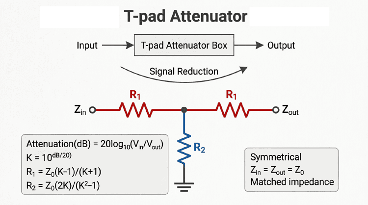
When designing passive attenuators, the standard T-pad and Pi-pad are the most common choices for fixed attenuation. However, when the requirement shifts from a fixed attenuation to a variable attenuator—such as a volume control or a continuously adjustable RF level setter—the standard T-pad becomes cumbersome. Changing the attenuation in a T-pad requires simultaneously adjusting three different resistors while maintaining a complex mathematical relationship to keep the impedance matched.
Enter the Bridged-T attenuator.
The Bridged-T is a clever variation of the standard T-pad that adds a fourth resistor “bridging” the input and output ports. This seemingly small addition provides a massive engineering advantage: it allows the series resistors to remain fixed at the characteristic impedance ($Z_0$), meaning only two resistors need to be varied to change the attenuation.
This unique property makes the Bridged-T the topology of choice for high-quality, constant-impedance volume controls, precision RF test equipment, and audio equalizers. This comprehensive guide will explore the structure, design equations, and practical applications of the Bridged-T attenuator.
What is a Bridged-T Attenuator?
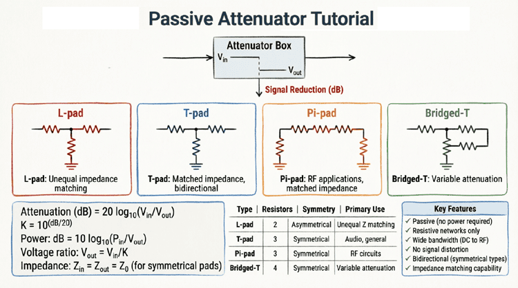
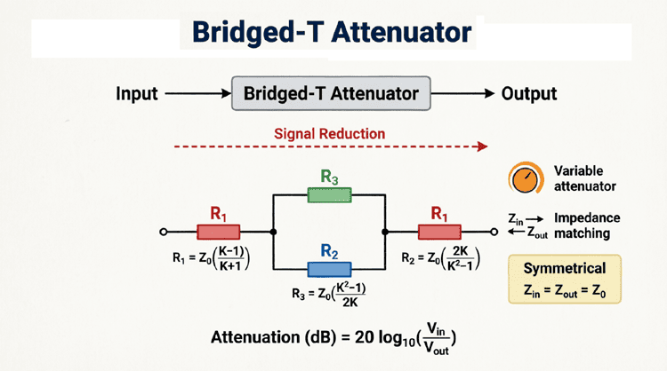
A Bridged-T attenuator is a four-resistor passive network consisting of two series resistors, one shunt resistor to ground, and one resistor bridging the input and output. Its primary advantage is that the series resistors can remain fixed at the characteristic impedance ($Z_0$), allowing for easy design of variable attenuators where only two resistors need to change to adjust the signal level.
Structure and Operation of the Bridged-T
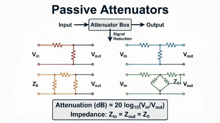
The Bridged-T gets its name from its physical layout, which looks like a standard T-pad with an additional resistor “bridged” across the top, connecting the input directly to the output.
The Four Resistors
- Input Series Resistor ($R_1$): Placed in series with the input signal. In a symmetrical Bridged-T, this is always equal to the characteristic impedance ($Z_0$).
- Output Series Resistor ($R_3$): Placed in series with the output signal. This is also always equal to $Z_0$.
- Shunt Resistor ($R_2$): Connected from the center node (between $R_1$ and $R_3$) to ground. This resistor varies inversely with the attenuation.
- Bridging Resistor ($R_4$): Connected directly from the input node to the output node, bypassing the center shunt resistor. This resistor varies directly with the attenuation.
The “Constant Impedance” Magic
In a standard T-pad, all three resistors must change value simultaneously to maintain impedance matching when adjusting attenuation. In a Bridged-T, because $R_1$ and $R_3$ are permanently fixed at $Z_0$, the input and output impedances remain perfectly matched to $Z_0$ regardless of the values of $R_2$ and $R_4$, provided $R_2$ and $R_4$ are adjusted in tandem according to their specific mathematical relationship.
This means you can build a variable attenuator using a simple dual-gang potentiometer or a switched resistor network for just $R_2$ and $R_4$, and the circuit will never lose its impedance match.
Design Formulas for the Symmetrical Bridged-T
Designing a symmetrical Bridged-T is remarkably straightforward compared to other topologies, precisely because two of the resistors are predetermined.
Step 1: Calculate the Attenuation Factor (K)
As with all attenuators, first convert the desired attenuation in decibels (dB) to a linear voltage ratio ($K$):
$$K = 10^{\frac{A_{dB}}{20}}$$
Note: $K$ is always > 1. For 6 dB, $K \approx 2.0$. For 20 dB, $K = 10.0$.
Step 2: Calculate the Resistor Values
For a symmetrical Bridged-T matched to characteristic impedance $Z_0$:
For the Series Resistors ($R_1$ and $R_3$):
$$R_1 = R_3 = Z_0$$
For the Shunt Resistor ($R_2$):
$$R_2 = \frac{Z_0}{K – 1}$$
For the Bridging Resistor ($R_4$):
$$R_4 = Z_0 \times (K – 1)$$
Notice the elegant symmetry: $R_2$ and $R_4$ are mathematical inverses of each other relative to $Z_0$. As attenuation increases ($K$ gets larger), $R_2$ gets smaller (shorting more signal to ground) and $R_4$ gets larger (blocking the bridge path).
Step-by-Step Practical Example
Let’s design a 50Ω, 20 dB symmetrical Bridged-T attenuator for an RF test setup.
Given:
- Characteristic Impedance ($Z_0$) = 50Ω
- Attenuation ($A_{dB}$) = 20 dB
Step 1: Calculate K
$$K = 10^{\frac{20}{20}} = 10^1 = 10.0$$
Step 2: Calculate Series Resistors
$$R_1 = R_3 = 50\Omega$$
Step 3: Calculate Shunt Resistor ($R_2$)
$$R_2 = \frac{50}{10 – 1} = \frac{50}{9} \approx \mathbf{5.56 \Omega}$$
Step 4: Calculate Bridging Resistor ($R_4$)
$$R_4 = 50 \times (10 – 1) = 50 \times 9 = \mathbf{450 \Omega}$$
Result:
To build this attenuator, you use two fixed 50Ω resistors for the series arms, a 5.56Ω resistor to ground, and a 450Ω resistor bridging the input and output.
If you later decide you need 6 dB of attenuation instead ($K = 2.0$), you only change $R_2$ and $R_4$:
- $R_2 = 50 / (2 – 1) = 50\Omega$
- $R_4 = 50 \times (2 – 1) = 50\Omega$
The 50Ω series resistors remain untouched!
The Bridged-T as a Variable Attenuator
The true superpower of the Bridged-T topology is its application in variable attenuators and volume controls.
Ganged Potentiometers
To create a continuously variable Bridged-T attenuator, engineers use a dual-gang potentiometer.
- One gang of the pot acts as $R_2$ (shunt to ground).
- The other gang acts as $R_4$ (the bridge).
Because the mathematical relationship between $R_2$ and $R_4$ is $R_2 \times R_4 = Z_0^2$ (derived from the formulas above), the potentiometer must be a special anti-logarithmic (reverse audio) taper or specifically engineered to follow this inverse curve. As the user turns the knob, $R_2$ decreases while $R_4$ increases simultaneously, keeping the input and output impedances perfectly locked at $Z_0$ throughout the entire rotation.
Switched Step Attenuators
For precision laboratory equipment, a “stepped” attenuator is used. A rotary switch selects different pairs of $R_2$ and $R_4$ resistors. Because $R_1$ and $R_3$ are fixed, the switch only needs to handle two poles instead of three (as required by a T-pad), making the switch cheaper, more reliable, and less prone to parasitic capacitance at high frequencies.
Bridged-T vs. Standard T-pad: A Direct Comparison
Why choose a Bridged-T over a standard T-pad?
| Feature | Standard T-pad | Bridged-T |
|---|---|---|
| Number of Resistors | 3 | 4 |
| Variable Attenuation | Requires 3 simultaneous changes | Requires only 2 changes |
| Series Resistor Values | Varies with attenuation | Fixed at $Z_0$ |
| High-Frequency Performance | Good | Excellent (fewer switch contacts in variable versions) |
| Component Count (Fixed) | Lower | Slightly higher |
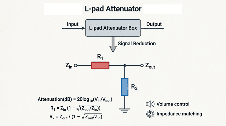
For fixed attenuators, the standard T-pad is usually preferred because it uses one less resistor. However, for variable attenuators, the Bridged-T is vastly superior due to the simplified switching or ganging requirements.
Practical Applications
1. High-Fidelity Audio Volume Controls
In high-end audio equipment, maintaining a constant input impedance is crucial for the performance of the preceding preamplifier stage. A Bridged-T volume control ensures that as you turn the volume down, the amplifier still “sees” the exact same load impedance, preventing frequency response anomalies and distortion.
2. RF and Microwave Test Equipment
Spectrum analyzers and network analyzers use internal Bridged-T networks for their input attenuation switches. Because the series resistors are fixed at 50Ω, the internal 50Ω transmission lines remain perfectly matched, minimizing signal reflections (VSWR) even when the user changes the attenuation from 0 dB to 60 dB.
3. Graphic Equalizers
The classic graphic equalizer uses a series of Bridged-T (or bridged-H for balanced audio) filter circuits. The slider on the equalizer adjusts the shunt and bridging resistors for a specific frequency band, allowing that band to be boosted or cut without altering the overall impedance of the audio chain.
4. Optical and Laser Power Control
In fiber optic and laser systems, variable optical attenuators (VOAs) often use electronic control circuits based on the Bridged-T topology to drive the physical attenuation mechanisms, ensuring linear control over the optical power while maintaining electrical impedance matching for the control signals.
Practical Considerations and Limitations
1. Power Dissipation
Just like the T-pad, the Bridged-T dissipates power as heat. The bridging resistor ($R_4$) and the shunt resistor ($R_2$) must be rated to handle the expected power. In high-attenuation settings, $R_2$ becomes very small and will dissipate the majority of the power. Ensure $R_2$ has an adequate wattage rating.
2. Parasitic Capacitance at High Frequencies
While the Bridged-T is excellent for RF, the physical layout is critical. The bridging resistor ($R_4$) physically crosses over the circuit, which can introduce parasitic capacitance to the ground plane. At microwave frequencies (GHz range), surface-mount (SMD) resistors and careful PCB layout (using coplanar waveguides) are mandatory to prevent the bridge resistor from acting as a capacitor.
3. Resistor Tolerances
Because the impedance match relies on the exact mathematical relationship between $R_2$ and $R_4$, resistor tolerances are critical. If $R_2$ is 5% too high and $R_4$ is 5% too low, the impedance match will degrade, causing signal reflections. Always use 1% (or better) metal film resistors for RF applications.
The Bridged-T attenuator is a brilliant evolution of the standard T-pad, specifically engineered to solve the complexities of variable attenuation. By fixing the series resistors at the characteristic impedance and utilizing a bridging resistor, it simplifies the mechanical and electrical design of adjustable attenuators while maintaining perfect bilateral impedance matching.
Key takeaways from this guide include:
- Structure: It uses four resistors: two fixed series resistors ($R_1 = R_3 = Z_0$), one variable shunt resistor ($R_2$), and one variable bridging resistor ($R_4$).
- Design Formulas: $R_2 = Z_0 / (K – 1)$ and $R_4 = Z_0 \times (K – 1)$. The relationship $R_2 \times R_4 = Z_0^2$ is the key to its constant-impedance property.
- Variable Attenuation: It is the preferred topology for ganged potentiometer volume controls and switched step attenuators because only two components need to change value.
- Applications: Widely used in high-end audio volume controls, RF test equipment input stages, and graphic equalizers.
- Trade-offs: While it requires one more resistor than a standard T-pad, the benefits in variable applications far outweigh the slight increase in component count.
Whether you are designing a boutique audio preamplifier, building a custom RF test fixture, or studying the inner workings of a spectrum analyzer, the Bridged-T attenuator is an essential circuit topology that perfectly balances mathematical elegance with practical engineering utility.