Passive Attenuators
Passive Attenuators: Signal Reduction Circuits
Introduction to Passive Attenuators
In the world of electronics and signal processing, there are countless situations where we need to reduce the amplitude of a signal without significantly distorting its waveform. Whether you’re protecting a sensitive receiver from a strong signal, matching voltage levels between circuit stages, or calibrating test equipment, passive attenuators provide the solution.
A passive attenuator is a resistive network designed to reduce signal strength by a specific amount while maintaining impedance matching between source and load. Unlike active attenuators that use amplifiers, passive attenuators rely solely on resistors, making them simple, reliable, and broadband in nature.
These circuits are fundamental building blocks in:
- RF and microwave systems for signal level control
- Audio equipment for volume control and level matching
- Test and measurement for protecting sensitive instruments
- Telecommunications for signal conditioning
- Antenna systems for impedance matching and signal reduction
Understanding passive attenuators is essential for any electronics engineer working with signal chains, RF systems, or precision measurements. This comprehensive guide will explore the principles, types, design calculations, and practical applications of passive attenuators.
What is a Passive Attenuator?
A passive attenuator is a resistive network that reduces signal amplitude by a specific amount (measured in decibels) while maintaining impedance matching between source and load. It uses only resistors (no active components), making it simple, reliable, and frequency-independent over a wide range.
Fundamental Principles of Attenuation
What is Attenuation?
Attenuation is the reduction in signal amplitude or power as it passes through a circuit or transmission medium. In the context of passive attenuators, we deliberately introduce controlled attenuation using resistive elements.
Attenuation is typically expressed in decibels (dB):
For Voltage:
$$A_{dB} = 20 \log_{10}\left(\frac{V_{out}}{V_{in}}\right)$$
For Power:
$$A_{dB} = 10 \log_{10}\left(\frac{P_{out}}{P_{in}}\right)$$
Where:
- $A_{dB}$ = Attenuation in decibels (negative value indicates loss)
- $V_{in}$, $V_{out}$ = Input and output voltages
- $P_{in}$, $P_{out}$ = Input and output powers
Common Attenuation Values:
- 3 dB = 0.707 voltage ratio (half power)
- 6 dB = 0.500 voltage ratio
- 10 dB = 0.316 voltage ratio
- 20 dB = 0.100 voltage ratio
- 40 dB = 0.010 voltage ratio
Key Characteristics of Passive Attenuators
1. Impedance Matching:
A well-designed attenuator maintains specific input and output impedances (typically 50Ω, 75Ω, or 600Ω). This prevents reflections and ensures maximum power transfer.
2. Reciprocity:
Passive attenuators are bilateral—they work the same in both directions. The attenuation is identical whether the signal flows from port 1 to port 2 or vice versa.
3. Frequency Response:
Since they use only resistors (no reactive components), ideal passive attenuators have flat frequency response from DC to very high frequencies. In practice, parasitic capacitance and inductance limit the upper frequency.
4. Power Handling:
Attenuators dissipate power as heat. The resistors must be rated to handle the expected power levels without damage or significant value drift.
5. Insertion Loss:
The attenuator itself introduces loss. Even a “0 dB” attenuator has some small insertion loss due to resistor tolerances and parasitic effects.
Types of Passive Attenuator Configurations
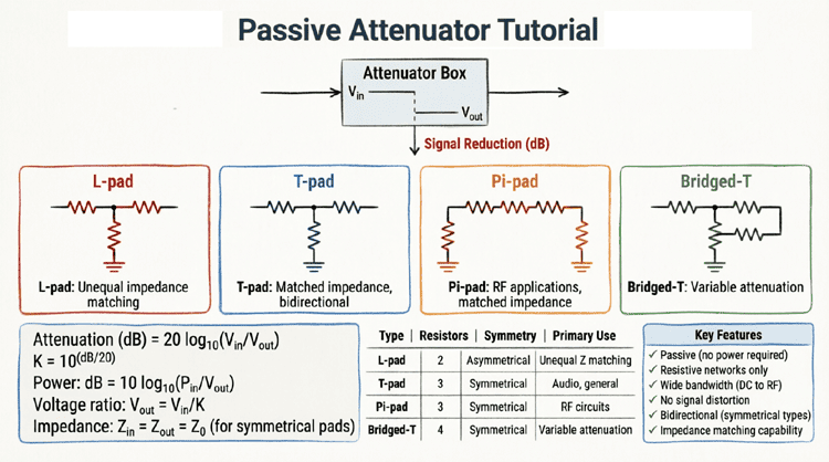
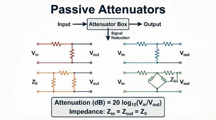
Passive attenuators can be configured in several topologies, each with specific advantages:
1. Unbalanced Attenuators
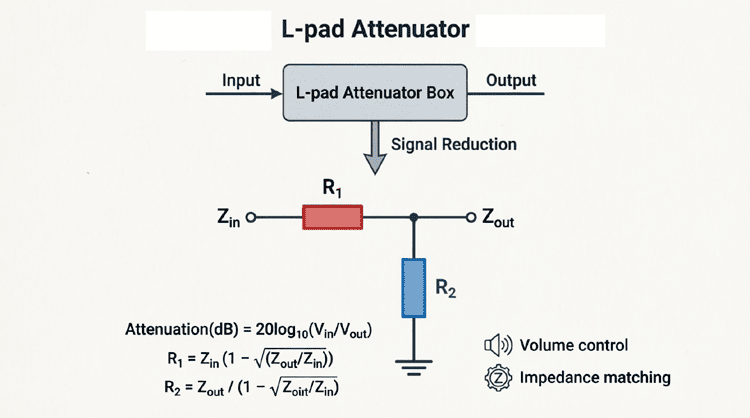
L-Pad (L-Network):
- Simplest configuration
- Two resistors in L-shape
- Matches impedance in one direction only
- Used for impedance matching between unequal impedances
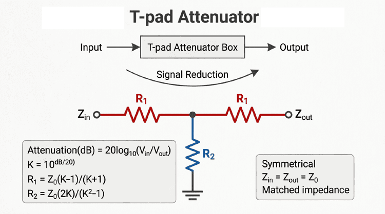
T-Pad (T-Network):
- Three resistors in T-configuration
- Symmetrical design
- Matches impedance in both directions
- Common in RF applications
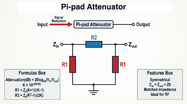
Pi-Pad (π-Network):
- Three resistors in Pi configuration
- Symmetrical design
- Better high-frequency performance than T-pad
- Easier to construct in some applications
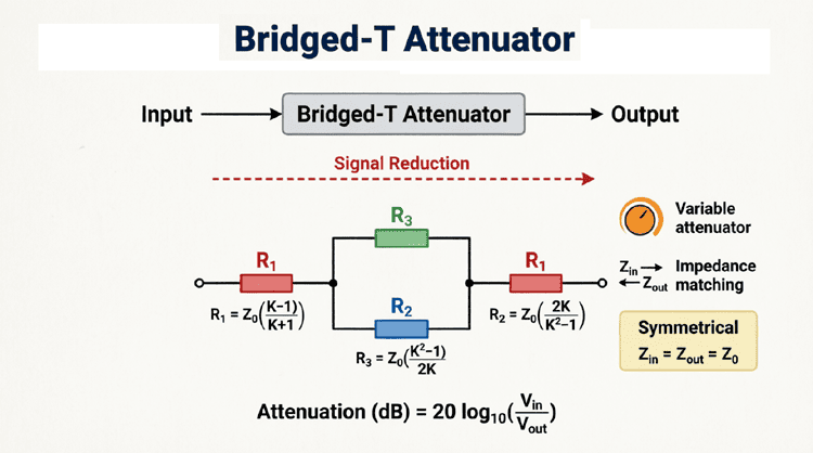
Bridged-T Attenuator:
- Four resistors in bridged-T configuration
- Variable attenuation capability
- Requires fewer resistor value changes for adjustment
- Used in precision applications
2. Balanced Attenuators
For balanced lines (like twisted pair or differential signals), balanced attenuators use symmetrical configurations:
H-Pad: Balanced version of T-pad
O-Pad: Balanced version of Pi-pad
Bridged-H: Balanced version of bridged-T
3. Step Attenuators
Multiple fixed attenuator sections switched in combination to provide variable attenuation in discrete steps (e.g., 0-60 dB in 1 dB steps).
Design Considerations for Passive Attenuators
Impedance Matching
The primary design goal is to maintain specific input and output impedances. For a symmetrical attenuator (same impedance on both ports):
Input Impedance: $Z_{in} = Z_0$ (when output is terminated in $Z_0$)
Output Impedance: $Z_{out} = Z_0$ (when input is terminated in $Z_0$)
Where $Z_0$ is the characteristic impedance (typically 50Ω or 75Ω for RF, 600Ω for audio).
Attenuation Factor (K)
The attenuation factor K is the voltage ratio:
$$K = \frac{V_{in}}{V_{out}} = 10^{\frac{A_{dB}}{20}}$$
For example:
- 6 dB attenuation: $K = 10^{6/20} = 10^{0.3} = 2.0$
- 20 dB attenuation: $K = 10^{20/20} = 10^1 = 10.0$
Power Dissipation
The attenuator dissipates the difference between input and output power:
$$P_{dissipated} = P_{in} – P_{out} = P_{in}\left(1 – \frac{1}{K^2}\right)$$
For a 10 dB attenuator with 1W input:
- $K = 10^{10/20} = 3.162$
- $P_{out} = 1W / 3.162^2 = 0.1W$
- $P_{dissipated} = 1W – 0.1W = 0.9W$
Resistors must be rated for this power dissipation with adequate safety margin.
Resistor Tolerances
Resistor tolerances directly affect attenuator accuracy:
- 1% resistors: Attenuation accuracy ±0.1 dB
- 5% resistors: Attenuation accuracy ±0.5 dB
- 10% resistors: Attenuation accuracy ±1.0 dB
For precision applications, use 1% or better tolerance resistors.
Practical Applications
1. RF Signal Level Control
In radio receivers, strong signals can overload the front-end. Fixed or variable attenuators protect sensitive components:
- Prevent mixer overload
- Reduce intermodulation distortion
- Protect low-noise amplifiers (LNAs)
2. Test and Measurement
Oscilloscopes, spectrum analyzers, and power meters have maximum input limits. Attenuators:
- Extend measurement range
- Protect expensive instruments
- Provide known reference levels
3. Audio Level Matching
Different audio equipment operates at different levels:
- Microphone level: -60 to -40 dBV
- Line level: -10 to +4 dBV
- Speaker level: +20 to +40 dBV
Attenuators match these levels without loading the source.
4. Antenna Systems
In transmission lines and antenna systems:
- Match impedances between components
- Reduce standing wave ratio (SWR)
- Provide isolation between stages
5. Signal Generator Output Control
Signal generators use output attenuators to:
- Provide precise output levels
- Maintain output impedance
- Protect output amplifiers
Advantages and Limitations
Advantages
- Simplicity: Only resistors required—no active components
- Broadband: Flat frequency response from DC to high frequencies
- Reliability: No power supply required, no active components to fail
- Linearity: Excellent linearity—no distortion or intermodulation
- Predictability: Performance easily calculated and verified
- Bidirectional: Works in both directions equally
Limitations
- Power Loss: Dissipates power as heat—inefficient
- Fixed Attenuation: Most designs provide fixed attenuation (unless switched)
- Size: High-power attenuators can be physically large
- Frequency Limits: Parasitic effects limit very high-frequency performance
- Impedance Constraints: Must be designed for specific impedance
Practical Example: Designing a 10 dB Attenuator
Problem: Design a symmetrical 50Ω, 10 dB attenuator.
Given:
- $Z_0 = 50\Omega$
- Attenuation = 10 dB
Step 1: Calculate K factor
$$K = 10^{10/20} = 10^{0.5} = 3.162$$
Step 2: For T-pad configuration
Using T-pad formulas:
$$R_1 = R_3 = Z_0 \times \frac{K-1}{K+1} = 50 \times \frac{3.162-1}{3.162+1} = 50 \times \frac{2.162}{4.162} = 25.97\Omega$$
$$R_2 = Z_0 \times \frac{2K}{K^2-1} = 50 \times \frac{2 \times 3.162}{3.162^2-1} = 50 \times \frac{6.324}{9.0-1} = 50 \times \frac{6.324}{8.0} = 39.53\Omega$$
Step 3: Select standard resistor values
- $R_1 = R_3 = 26\Omega$ (1% tolerance)
- $R_2 = 39.5\Omega$ (1% tolerance)
Step 4: Verify
Actual attenuation with standard values:
$$K_{actual} = \frac{26 + 39.5 + 26}{26} = 3.52$$
$$A_{dB} = 20 \log_{10}(3.52) = 10.93 \text{ dB}$$
Close enough for most applications. For better accuracy, use resistor networks or trimmer resistors.
Passive attenuators are fundamental components in electronic systems, providing controlled signal reduction while maintaining impedance matching. Their simplicity, reliability, and broadband performance make them indispensable in RF, audio, and measurement applications.
Key takeaways from this guide include:
- Definition: Passive attenuators use resistive networks to reduce signal amplitude by a specific dB amount while maintaining impedance matching
- Types: L-pad, T-pad, Pi-pad, and bridged-T configurations, each with specific advantages for different applications
- Design Principles:
- Maintain input/output impedance ($Z_0$)
- Calculate attenuation factor $K = 10^{(A_{dB}/20)}$
- Ensure adequate power dissipation ratings
- Use precision resistors for accuracy
- Applications: RF signal control, test equipment protection, audio level matching, antenna systems, and signal generation
- Advantages: Simplicity, broadband response, reliability, linearity, and bidirectional operation
- Limitations: Power dissipation, fixed attenuation (typically), size for high power, and frequency limits
Understanding passive attenuators enables you to design effective signal conditioning circuits, protect sensitive equipment, and ensure proper impedance matching throughout your signal chain. Whether you’re working with RF systems, audio equipment, or precision measurements, passive attenuators provide the controlled, predictable signal reduction essential for optimal system performance.