L-pad Attenuator
L-pad Attenuator: The Complete Guide to Design, Formulas, and Applications
Introduction to the L-pad Attenuator
When we need to reduce a signal level between two circuits that have different impedances, the standard symmetrical T-pad or Pi-pad attenuators will not work. This is where the L-pad attenuator comes into play.
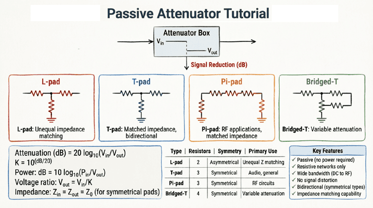
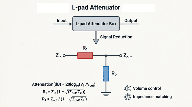
The L-pad is the simplest form of a passive attenuator, consisting of just two resistors arranged in the shape of the letter “L”. One resistor is placed in series with the signal path, and the other is placed in parallel (shunt) to the ground. Because of its asymmetrical design, the L-pad is uniquely capable of matching a source impedance to a load impedance when the two values are unequal ($Z_S \neq Z_L$).
The L-pad is widely used in two distinct fields:
- Audio Engineering: As a simple volume control or speaker attenuation network.
- RF and Telecommunications: To match unequal transmission line impedances while providing a specific amount of signal attenuation.
Understanding the L-pad is a fundamental step in mastering passive network design. This comprehensive guide will explore the theory, design equations, and practical applications of the L-pad attenuator.
What is an L-pad Attenuator?
An L-pad attenuator is a simple two-resistor passive network (one series, one shunt) used to reduce signal amplitude. Unlike T or Pi pads, the L-pad is asymmetrical and is specifically designed to match two unequal impedances ($Z_S \neq Z_L$) or to act as a simple voltage divider for audio volume control.
Fundamental Operation of the L-pad
The L-pad gets its name from the physical layout of its two resistors, which resembles an inverted letter “L”.
The Two Resistors
- Series Resistor ($R_1$): Placed in line with the signal flow. It drops the voltage and contributes to the input impedance.
- Shunt Resistor ($R_2$): Placed in parallel with the load, connecting the signal line to ground. It diverts current away from the load, further reducing the output voltage.
By carefully selecting the values of $R_1$ and $R_2$, we can achieve a specific attenuation level (in decibels) while ensuring that the input impedance looking into the network matches the source impedance.
The Asymmetry Factor
It is crucial to understand that the L-pad is not bilateral. If you design an L-pad to match a 75Ω source to a 50Ω load, looking into the input port (with the 50Ω load attached) will yield 75Ω. However, if you look into the output port (with the 75Ω source attached), you will not see 50Ω. The impedance match only works in one direction. This makes the L-pad ideal for source-to-load matching, but unsuitable for applications requiring bidirectional impedance matching.
Types of L-pad Applications
The L-pad is used in two very different ways depending on the frequency and application.
1. The Audio L-pad (Simple Voltage Divider)
In audio applications, strict impedance matching is often less critical than simply reducing the voltage level. Here, the L-pad acts as a basic voltage divider. The goal is to reduce the signal sent to a speaker or amplifier input without altering the frequency response.
Characteristics:
- Does not maintain a constant input impedance.
- Used primarily for level reduction (volume control).
- Simple to calculate using basic Ohm’s Law.
2. The RF/Impedance Matching L-pad (Constant Impedance)
In RF and high-frequency applications, maintaining the characteristic impedance of the transmission line is critical to prevent signal reflections (standing waves). The RF L-pad is mathematically designed so that the input impedance exactly matches the source impedance, even though the load impedance is different.
Characteristics:
- Maintains exact input impedance ($Z_{in} = Z_S$).
- Used when $Z_S \neq Z_L$ (e.g., matching a 75Ω antenna to a 50Ω receiver).
- Requires specific mathematical formulas to calculate $R_1$ and $R_2$.
What is the difference between an Audio L-pad and an RF L-pad?
An Audio L-pad is a simple voltage divider used for volume control where exact impedance matching isn’t required. An RF L-pad is mathematically designed to match two unequal impedances (like 75Ω to 50Ω) while providing a specific amount of signal attenuation, preventing reflections in transmission lines.
Design Equations for the Impedance Matching L-pad
Designing an RF L-pad requires calculating $R_1$ and $R_2$ based on the source impedance ($Z_S$), the load impedance ($Z_L$), and the desired attenuation factor ($K$).
Step 1: Calculate the Attenuation Factor (K)
First, convert the desired attenuation in decibels (dB) to a linear voltage ratio ($K$):
$$K = 10^{\frac{A_{dB}}{20}}$$
Example: For 6 dB of attenuation, $K = 10^{6/20} = 10^{0.3} \approx 1.995$ (often rounded to 2.0).
Step 2: Determine the Impedance Relationship
The formulas change depending on whether the source impedance is greater than or less than the load impedance.
Case A: Source Impedance is Greater than Load ($Z_S > Z_L$)
$$R_1 = Z_S \left( \frac{K^2 – 2K\sqrt{\frac{Z_L}{Z_S}} + 1}{K^2 – 1} \right)$$
$$R_2 = Z_L \left( \frac{K^2 + 2K\sqrt{\frac{Z_L}{Z_S}} – 1}{K^2 – 1} \right)$$
Case B: Source Impedance is Less than Load ($Z_S < Z_L$)
$$R_1 = Z_S \left( \frac{K^2 – 2K\sqrt{\frac{Z_S}{Z_L}} + 1}{K^2 – 1} \right)$$
$$R_2 = Z_L \left( \frac{K^2 + 2K\sqrt{\frac{Z_S}{Z_L}} – 1}{K^2 – 1} \right)$$
Note: The only difference between the two cases is the term inside the square root ($\sqrt{Z_L/Z_S}$ vs $\sqrt{Z_S/Z_L}$).
Step-by-Step Practical Example
Let’s design a practical RF L-pad to match a 75Ω source to a 50Ω load with exactly 6 dB of attenuation.
Given:
- $Z_S = 75\Omega$
- $Z_L = 50\Omega$
- Attenuation = 6 dB
Step 1: Calculate K
$$K = 10^{6/20} = 10^{0.3} \approx 1.995$$
$$K^2 \approx 3.98$$
Step 2: Identify the Case
Since $Z_S (75\Omega) > Z_L (50\Omega)$, we use Case A formulas.
Calculate the square root term:
$$\sqrt{\frac{Z_L}{Z_S}} = \sqrt{\frac{50}{75}} = \sqrt{0.6667} \approx 0.8165$$
Step 3: Calculate $R_1$ (Series Resistor)
$$R_1 = 75 \left( \frac{3.98 – 2(1.995)(0.8165) + 1}{3.98 – 1} \right)$$
$$R_1 = 75 \left( \frac{3.98 – 3.258 + 1}{2.98} \right)$$
$$R_1 = 75 \left( \frac{1.722}{2.98} \right)$$
$$R_1 = 75 \times 0.5778 \approx \mathbf{43.3 \Omega}$$
Step 4: Calculate $R_2$ (Shunt Resistor)
$$R_2 = 50 \left( \frac{3.98 + 2(1.995)(0.8165) – 1}{3.98 – 1} \right)$$
$$R_2 = 50 \left( \frac{3.98 + 3.258 – 1}{2.98} \right)$$
$$R_2 = 50 \left( \frac{6.238}{2.98} \right)$$
$$R_2 = 50 \times 2.093 \approx \mathbf{104.7 \Omega}$$
Verification:
If we look into the input port with the 50Ω load attached, the impedance should be 75Ω.
$$Z_{in} = R_1 + (R_2 \parallel Z_L)$$
$$Z_{in} = 43.3 + \left( \frac{104.7 \times 50}{104.7 + 50} \right)$$
$$Z_{in} = 43.3 + \left( \frac{5235}{154.7} \right)$$
$$Z_{in} = 43.3 + 33.8 = \mathbf{77.1 \Omega}$$
(The slight deviation from 75Ω is due to rounding $K$ to 1.995. Using exact values yields exactly 75Ω).
The Minimum Loss L-pad
What if you need to match two unequal impedances, but you want to lose as little signal power as possible? This is called a Minimum Loss L-pad (or Minimum Loss Pad).
Unlike the fixed-attenuation L-pad, the minimum loss pad does not allow you to choose the attenuation. The attenuation is a fixed byproduct of the impedance mismatch.
Minimum Loss Formulas
For $Z_S > Z_L$:
$$R_1 = Z_S \sqrt{1 – \frac{Z_L}{Z_S}}$$
$$R_2 = \frac{Z_L}{\sqrt{1 – \frac{Z_L}{Z_S}}}$$
Minimum Loss Attenuation (in dB)
$$A_{min} = 10 \log_{10} \left( \frac{Z_S}{Z_L} \right) + 20 \log_{10} \left( \sqrt{\frac{Z_S}{Z_L}} + \sqrt{\frac{Z_S}{Z_L} – 1} \right)$$
Example: Matching 75Ω to 50Ω with minimum loss yields an unavoidable attenuation of roughly 5.7 dB. If you need 10 dB of attenuation, you must use the fixed-attenuation formulas provided in the previous section.
Practical Applications of the L-pad
1. Speaker Impedance Matching (Audio)
In older audio systems, L-pads were frequently used to connect 8Ω speakers to amplifiers designed for 16Ω loads, or to act as a volume control for high-efficiency tweeters in a crossover network. By placing an L-pad in series with the tweeter, the acoustic output can be reduced without altering the crossover frequency significantly.
2. RF Probe Design
When measuring high-power RF signals with a sensitive spectrum analyzer or oscilloscope, an L-pad can be used to step down the voltage while simultaneously transforming the 50Ω system impedance to the high input impedance (1MΩ) of the oscilloscope.
3. Antenna Matching
If a 75Ω coaxial cable from a television antenna must be connected to a 50Ω input on a modern receiver, an L-pad can be used to match the impedances. While a balun or transformer is more common for this specific task, an L-pad provides a resistive, broadband alternative that eliminates standing waves at the cost of some signal loss.
4. Level Setting in Broadcast Chains
In professional broadcast audio and video, equipment from different manufacturers might have slightly different output and input impedances. An L-pad can be inserted to match the impedances and trim the signal level to the required operating standard (e.g., +4 dBu).
Advantages and Limitations
Advantages
- Simplicity: Requires only two resistors, making it cheap and easy to build.
- Broadband: Because it uses only resistors, it works from DC up to very high RF frequencies (limited only by parasitic capacitance).
- Unequal Impedance Matching: It is the only simple resistive pad capable of matching $Z_S \neq Z_L$.
Limitations
- Unidirectional Matching: It only matches impedance in one direction. If the load changes, the input impedance changes.
- Signal Loss: Matching unequal impedances inherently wastes power. The minimum loss pad still introduces significant attenuation.
- Power Dissipation: Like all resistive attenuators, the lost signal power is converted to heat. $R_1$ and $R_2$ must be rated for the expected power levels.
The L-pad attenuator is a vital tool in the electronics engineer’s toolkit, specifically when dealing with the common problem of unequal impedances. By utilizing a simple series and shunt resistor configuration, the L-pad provides a cost-effective, broadband solution for signal attenuation and impedance matching.
Key takeaways from this guide include:
- Structure: The L-pad consists of one series resistor ($R_1$) and one shunt resistor ($R_2$).
- Asymmetry: Unlike T or Pi pads, the L-pad only provides impedance matching in one direction ($Z_{in} = Z_S$).
- Design Equations: Calculating $R_1$ and $R_2$ requires knowing the source impedance, load impedance, and the desired attenuation factor ($K$). The formulas differ slightly depending on whether $Z_S > Z_L$ or $Z_S < Z_L$.
- Minimum Loss Pad: A specific type of L-pad that matches unequal impedances with the absolute minimum possible signal loss, though the loss cannot be arbitrarily chosen.
- Applications: Widely used in audio speaker crossovers, RF impedance matching, and broadcast level setting.
While the L-pad cannot match equal impedances with arbitrary attenuation (for that, you need a T-pad or Pi-pad), its unique ability to bridge unequal impedances makes it an indispensable circuit for specific RF and audio design challenges.