The Wien Bridge Oscillator
The Wien Bridge Oscillator: Complete Guide to Low-Distortion Audio Oscillators
Introduction to the Wien Bridge Oscillator
The Wien Bridge Oscillator stands as one of the most elegant and widely used oscillator circuits in audio engineering and test equipment. Invented by German physicist Max Wien in 1891 and later refined by William Hewlett (co-founder of Hewlett-Packard) in his 1939 master’s thesis, this circuit revolutionized audio testing and measurement.
Hewlett’s Wien bridge oscillator design became the foundation for the HP 200A Audio Oscillator, HP’s first commercial product. This simple yet brilliant circuit provided low-distortion sine waves at audio frequencies, enabling accurate testing of audio equipment and establishing HP as a leader in electronic test equipment.
The Wien bridge oscillator is renowned for its ability to produce exceptionally clean, low-distortion sine waves across the entire audio spectrum (20 Hz to 20 kHz). Unlike the RC phase shift oscillator which requires high gain and produces more distortion, the Wien bridge topology uses a balanced bridge network that requires only a gain of 3, resulting in superior waveform purity.
This comprehensive guide will explore the Wien bridge oscillator’s unique topology, mathematical principles, amplitude stabilization techniques, and practical design considerations that have made it the gold standard for audio frequency generation for over 80 years.
What is a Wien Bridge Oscillator?
A Wien bridge oscillator is an RC oscillator circuit that uses a bridge network consisting of series and parallel RC combinations to provide frequency-selective feedback. It requires a minimum gain of only 3 and produces very low-distortion sine waves, making it ideal for audio test equipment and precision signal generation from 20 Hz to 20 kHz.
Circuit Topology and Operation
The Wien Bridge Network
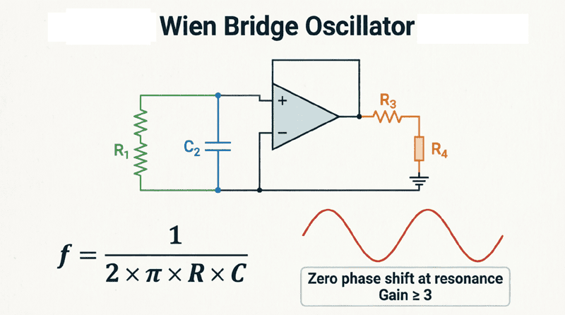
The heart of the Wien bridge oscillator is the Wien bridge network, a frequency-selective circuit consisting of four arms:
- Series RC Network: A resistor ($R_1$) and capacitor ($C_1$) connected in series
- Parallel RC Network: A resistor ($R_2$) and capacitor ($C_2$) connected in parallel
- Two Gain-Setting Resistors: $R_3$ and $R_4$ that set the amplifier gain
This bridge configuration is connected between the output and input of a non-inverting amplifier (typically an Op-Amp).
The Balanced Bridge Condition
At a specific frequency, the Wien bridge network exhibits a unique property: the phase shift through the network is exactly 0 degrees, and the attenuation is exactly 1/3.
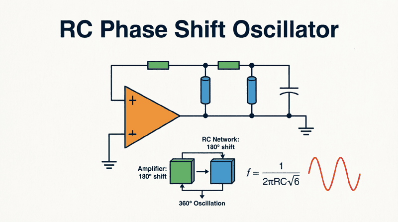
This is fundamentally different from the RC phase shift oscillator, which requires 180 degrees of phase shift and has an attenuation of 1/29. The Wien bridge’s lower attenuation (1/3 vs 1/29) means the amplifier needs much less gain (3 vs 29), resulting in:
- Lower distortion
- Better stability
- Cleaner output waveform
Circuit Configuration
The standard Wien bridge oscillator uses:
- Non-Inverting Amplifier: An Op-Amp configured for non-inverting operation
- Positive Feedback: The Wien bridge network provides frequency-selective positive feedback
- Negative Feedback: A resistive divider sets the gain to exactly 3
The output of the Op-Amp is fed back to the non-inverting input (+) through the Wien bridge network. Simultaneously, negative feedback through resistors $R_3$ and $R_4$ sets the closed-loop gain.
Why does the Wien bridge oscillator produce lower distortion than the RC phase shift oscillator?
The Wien bridge requires a gain of only 3 (compared to 29 for RC phase shift), meaning the amplifier operates with less gain margin. This allows for more precise amplitude control and less waveform clipping, resulting in significantly lower harmonic distortion (typically < 0.1% vs 1-5% for RC phase shift).
Mathematical Analysis of the Wien Bridge
Frequency of Oscillation
For the standard Wien bridge oscillator where $R_1 = R_2 = R$ and $C_1 = C_2 = C$, the frequency of oscillation is:
$f_r = \frac{1}{2\pi R C}$
Where:
- $f_r$ = Frequency of oscillation in Hertz (Hz)
- $R$ = Resistance in Ohms ($\Omega$)
- $C$ = Capacitance in Farads (F)
Notice the simplicity of this formula compared to the RC phase shift oscillator’s $f_r = \frac{1}{2\pi R C \sqrt{6}}$. The Wien bridge eliminates the $\sqrt{6}$ factor, making frequency calculations more straightforward.
Derivation of the Frequency Formula
The transfer function of the Wien bridge network (from output to non-inverting input) is:
$\beta(j\omega) = \frac{Z_p}{Z_s + Z_p}$
Where:
- $Z_s = R + \frac{1}{j\omega C}$ (series impedance)
- $Z_p = \frac{R}{1 + j\omega R C}$ (parallel impedance)
At the resonant frequency, the imaginary parts cancel, leaving only the real part. Solving for when the phase shift is 0°:
$\omega_r = \frac{1}{R C}$
Converting to frequency:
$f_r = \frac{\omega_r}{2\pi} = \frac{1}{2\pi R C}$
Gain Requirement
At the resonant frequency, the Wien bridge network attenuates the signal by exactly 1/3. Therefore, to satisfy the Barkhausen criterion ($A_v \times \beta = 1$), the amplifier must provide a gain of exactly 3.
For a non-inverting Op-Amp configuration:
$A_v = 1 + \frac{R_3}{R_4} = 3$
Therefore:
$\frac{R_3}{R_4} = 2$
Or:
$R_3 = 2 R_4$
This simple ratio is easy to implement with precision resistors, ensuring stable oscillation.
Attenuation at Resonance
At $f_r$, the feedback factor $\beta$ is:
$\beta = \frac{1}{3}$
This means that 1/3 of the output voltage is fed back to the non-inverting input. With a gain of 3, the loop gain is exactly 1, sustaining oscillations.
Practical Design Example: 1 kHz Wien Bridge Oscillator
Let’s design a practical Wien bridge oscillator operating at 1 kHz with low distortion using a TL072 dual Op-Amp.
Step 1: Define Specifications
- Target Frequency ($f_r$): 1000 Hz (1 kHz)
- Supply Voltage: $\pm 15V$ (Dual supply for the Op-Amp)
- Active Device: TL072 (Low noise, JFET-input, excellent for audio)
- Target Distortion: < 0.1%
Step 2: Select the Capacitor
Choose a stable, low-loss capacitor for the Wien bridge network. For audio frequencies, polystyrene or polypropylene capacitors are ideal due to their low dielectric absorption and excellent stability.
$C = 10 \text{ nF}$ ($10 \times 10^{-9}$ F)
Step 3: Calculate the Resistor Value
Rearrange the frequency formula to solve for $R$:
$R = \frac{1}{2\pi f_r C}$
$R = \frac{1}{2\pi \times 1000 \times 10 \times 10^{-9}}$
$R = \frac{1}{6.283 \times 10^{-5}}$
$R \approx 15,915 \text{ } \Omega$
Use standard value: $R = 16 \text{ k}\Omega$
(Recalculating exact frequency with 16k: $f = 1 / (2\pi \times 16000 \times 10n) = 994.7 \text{ Hz}$. Very close to 1 kHz. For exact frequency, use a 15k resistor in series with a 2k trimmer potentiometer).
Step 4: Design the Gain Network
We need a gain of exactly 3. Using the non-inverting gain formula:
$A_v = 1 + \frac{R_3}{R_4} = 3$
Therefore: $\frac{R_3}{R_4} = 2$
Choose $R_4 = 10 \text{ k}\Omega$
Then $R_3 = 20 \text{ k}\Omega$
Use standard values:
- $R_4 = 10 \text{ k}\Omega$ (precision 1%)
- $R_3 = 20 \text{ k}\Omega$ (precision 1%)
Step 5: Amplitude Stabilization
For low distortion, we must implement amplitude stabilization. The classic method uses a small incandescent lamp or a pair of back-to-back diodes.
Diode Stabilization Method:
Replace $R_3$ with two resistors in series:
- $R_{3a} = 15 \text{ k}\Omega$
- $R_{3b} = 5 \text{ k}\Omega$
Place two 1N4148 diodes in parallel with $R_{3b}$, facing in opposite directions.
At startup, the diodes are off, giving a gain slightly higher than 3 to ensure oscillation starts. As the amplitude increases and reaches the diode threshold (~0.7V), the diodes conduct, reducing the effective resistance and stabilizing the gain at exactly 3.
Step 6: Complete Circuit Assembly
- Connect the Wien bridge network (two 16k resistors and two 10nF capacitors) between the output and non-inverting input (+).
- Connect the gain-setting network ($R_4 = 10k$ to ground, $R_{3a} + R_{3b}$ with diodes to output) between output and inverting input (-).
- Apply $\pm 15V$ to the Op-Amp power pins.
- Add decoupling capacitors (0.1 µF) close to the power pins.
Amplitude Stabilization Techniques
Achieving low distortion in a Wien bridge oscillator requires precise amplitude control. If the gain is too high, the output clips; if too low, oscillations cease. Several techniques exist for automatic amplitude stabilization:
1. Incandescent Lamp (Classic HP 200A Method)
William Hewlett’s original design used a tiny incandescent lamp as part of the gain-setting network. The lamp’s filament resistance increases with temperature.
Operation:
- At startup: Filament is cold, resistance is low, gain > 3, oscillations start
- As amplitude increases: Filament heats up, resistance increases, gain decreases
- At equilibrium: Gain stabilizes at exactly 3
Advantages:
- Extremely low distortion (< 0.01%)
- Smooth, continuous control
- Very stable amplitude
Disadvantages:
- Slow response time (thermal inertia)
- Bulky and fragile
- Not suitable for integrated circuits
2. Back-to-Back Diodes (Modern Method)
Two small-signal diodes (e.g., 1N4148) are placed in parallel with a portion of the feedback resistor, facing in opposite directions.
Operation:
- Low amplitude: Diodes are reverse-biased (off), gain is high
- High amplitude: Diodes conduct during peaks, reducing effective resistance and gain
- Equilibrium: Gain stabilizes at 3
Advantages:
- Compact and inexpensive
- Fast response
- Easy to implement
Disadvantages:
- Slightly higher distortion than lamp (~0.1%)
- Diode forward voltage varies with temperature
3. JFET as Voltage-Controlled Resistor
A JFET (e.g., 2N5457) is placed in the feedback path. The output amplitude is rectified and filtered to create a DC control voltage that biases the JFET’s gate, adjusting its channel resistance.
Operation:
- Output amplitude is sensed and converted to DC
- Higher amplitude → more negative gate voltage → higher JFET resistance → lower gain
- Lower amplitude → less negative gate voltage → lower JFET resistance → higher gain
Advantages:
- Very low distortion (< 0.05%)
- Fast response
- Solid-state (no moving parts)
- Suitable for IC implementation
Disadvantages:
- More complex circuit
- Requires additional components (rectifier, filter)
- JFET characteristics vary between devices
4. Automatic Gain Control (AGC) with Op-Amp
A dedicated AGC circuit using a second Op-Amp, a precision rectifier, and a voltage-controlled amplifier (VCA) or multiplier IC provides the most sophisticated amplitude control.
Advantages:
- Extremely low distortion (< 0.001%)
- Precise amplitude control
- Programmable amplitude
Disadvantages:
- Complex and expensive
- Requires multiple ICs
- Overkill for most applications
What is the best amplitude stabilization method for a Wien bridge oscillator?
For the lowest distortion, an incandescent lamp (as used in the classic HP 200A) provides the best performance (< 0.01% THD). For modern designs, a JFET-based AGC circuit offers an excellent compromise between performance (< 0.05% THD) and practicality. For simple applications, back-to-back diodes are adequate (~0.1% THD).
Advantages and Disadvantages
Advantages
- Very Low Distortion: The Wien bridge oscillator can achieve distortion levels below 0.1%, and with proper stabilization, below 0.01%. This makes it ideal for audio testing and measurement.
- Excellent Frequency Stability: The balanced bridge configuration provides good frequency stability, especially when using precision components.
- Wide Frequency Range: By using switched capacitors and variable resistors, a single Wien bridge oscillator can cover the entire audio spectrum (20 Hz to 20 kHz) and beyond.
- Easy Frequency Tuning: Frequency can be smoothly adjusted using a dual-gang potentiometer (for $R_1$ and $R_2$) or a dual-gang variable capacitor.
- Simple Gain Requirement: Only a gain of 3 is required, which is easy to achieve with minimal distortion.
- Good Amplitude Stability: With proper stabilization, the output amplitude remains constant over the entire frequency range.
Disadvantages
- Requires Amplitude Stabilization: Without automatic gain control, the circuit will either fail to oscillate or produce a clipped, distorted output.
- Component Matching: For best performance, the two resistors ($R_1$ and $R_2$) and two capacitors ($C_1$ and $C_2$) in the Wien network should be well-matched. Mismatched components can cause frequency errors and increased distortion.
- Limited to Audio Frequencies: While Wien bridge oscillators can operate up to about 1 MHz, they are primarily designed for audio frequencies. For RF applications, LC oscillators are more suitable.
- Sensitivity to Component Tolerances: Frequency accuracy depends on the precision of the RC components. High-precision applications require 1% or better tolerance components.
- Startup Time: With amplitude stabilization circuits (especially lamp-based), there may be a delay of several seconds before the output stabilizes.
Real-World Applications
1. Audio Test Equipment
The Wien bridge oscillator is the heart of most audio signal generators and distortion analyzers. Its low distortion and wide frequency range make it perfect for:
- Testing audio amplifiers
- Measuring speaker frequency response
- Calibrating audio measurement equipment
- Generating reference tones
2. Function Generators
Bench-top function generators use Wien bridge oscillators (often with automatic frequency control) to produce clean sine waves. The output can then be shaped into square and triangle waves using additional circuitry.
3. Bridge Circuits and Measurement
The Wien bridge itself (without the oscillator) is used as a precision measurement circuit for:
- Measuring capacitance
- Measuring frequency
- Audio frequency bridges
- Impedance measurement
4. Musical Instruments and Synthesizers
Vintage analog synthesizers and electronic organs often used Wien bridge oscillators to generate pure sine wave tones, which were then filtered and shaped to create various instrument sounds.
5. Educational and Laboratory Use
The Wien bridge oscillator is a standard experiment in university electronics laboratories, teaching students about:
- Oscillator theory
- Feedback principles
- Amplitude stabilization
- Frequency-selective networks
Comparison: Wien Bridge vs. RC Phase Shift
| Feature | Wien Bridge Oscillator | RC Phase Shift Oscillator |
|---|---|---|
| Minimum Gain | 3 | 29 |
| Distortion | Very low (< 0.1%) | Moderate (1-5%) |
| Frequency Stability | Good | Fair |
| Amplitude Stability | Excellent (with AGC) | Poor |
| Circuit Complexity | Moderate | Simple |
| Component Count | Higher (bridge network) | Lower (ladder network) |
| Frequency Tuning | Easy (dual-gang pot) | Moderate |
| Applications | Precision audio test | Simple tone generation |
Summary: Choose the Wien bridge for low-distortion, precision audio applications. Choose the RC phase shift for simple, low-cost oscillators where distortion is not critical.
The Wien bridge oscillator represents the pinnacle of RC oscillator design for audio applications. Its elegant bridge topology, requiring only a gain of 3 and providing excellent frequency selectivity, has made it the standard for low-distortion sine wave generation for over eight decades.
Key Takeaways:
- Topology: Uses a balanced bridge network with series and parallel RC combinations to provide 0° phase shift and 1/3 attenuation at resonance.
- Frequency Formula: $f_r = \frac{1}{2\pi R C}$ (simple and elegant)
- Gain Requirement: Minimum gain of 3, easily achieved with $R_3 = 2R_4$ in a non-inverting Op-Amp configuration.
- Amplitude Stabilization: Critical for low distortion. Best methods include incandescent lamp (classic), JFET AGC (modern), or back-to-back diodes (simple).
- Primary Advantages:
- Very low distortion (< 0.1%)
- Excellent frequency stability
- Wide tuning range
- Simple gain requirement
- Primary Disadvantages:
- Requires amplitude stabilization circuit
- Component matching important
- Limited to audio frequencies (< 1 MHz)
- Applications: Audio test equipment, function generators, bridge measurement circuits, musical instruments, and educational laboratories.
The Wien bridge oscillator’s legacy continues today in modern test equipment and audio systems. Whether you’re designing a precision audio analyzer, building a function generator, or simply need a clean sine wave for testing, the Wien bridge topology remains the gold standard for audio frequency generation.