Pi-pad Attenuator
Pi-pad Attenuator: The Complete Guide to Design, Formulas, and Applications
Introduction to the Pi-pad Attenuator
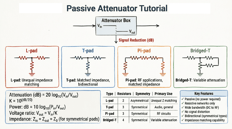
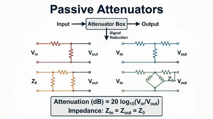
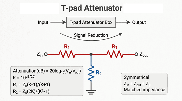
In the realm of passive resistive networks, the Pi-pad attenuator (often written as π-pad) stands as the elegant dual to the T-pad. While the T-pad uses two series resistors and one shunt resistor, the Pi-pad flips this topology, utilizing two shunt resistors and one series resistor. Arranged to resemble the Greek letter Pi (π), this symmetrical, bilateral network is a staple in RF engineering, video signal distribution, and high-impedance audio applications.
Like its T-pad counterpart, the symmetrical Pi-pad is designed to provide a precise amount of signal attenuation (measured in decibels) while maintaining a constant, matched characteristic impedance ($Z_0$) at both its input and output ports. Because it is perfectly symmetrical, it is bilateral, meaning it can be inserted into a transmission line in either direction without altering its electrical characteristics.
The Pi-pad is particularly favored in applications where the characteristic impedance is relatively high (such as 75Ω video systems or 600Ω professional audio), as its resistor values remain practical and easy to manufacture even at high levels of attenuation. This comprehensive guide will explore the structure, mathematical design, and practical implementations of the Pi-pad attenuator.
What is a Pi-pad Attenuator?
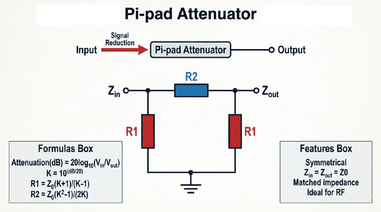
A Pi-pad (π-pad) attenuator is a symmetrical, bilateral passive network consisting of three resistors: two shunt resistors (connected to ground at the input and output) and one series resistor (connecting the input to the output). It is designed to reduce signal amplitude by a specific decibel (dB) amount while maintaining a constant characteristic impedance ($Z_0$) at both ports.
Structure and Operation of the Pi-pad
The name “Pi-pad” is derived from the physical layout of its three resistors, which resembles the Greek letter π (Pi). If you visualize a standard transmission line, the two shunt resistors look like the two vertical legs of the Pi, and the series resistor forms the horizontal top bar.
The Three Resistors
- Input Shunt Resistor ($R_1$): Connected from the input signal line directly to ground. It draws a specific amount of current from the source, helping to set the input impedance.
- Output Shunt Resistor ($R_3$): Connected from the output signal line directly to ground. In a symmetrical Pi-pad, $R_3$ is exactly equal to $R_1$.
- Series Resistor ($R_2$): Placed in series between the input and output nodes, bridging the two shunt resistors. It drops the voltage and completes the attenuation network.
Bilateral Symmetry
Just like the T-pad, the symmetrical Pi-pad is bilateral. If you terminate the output port with the characteristic impedance ($Z_0$), the impedance looking into the input port will also be exactly $Z_0$. This symmetry is vital in RF and video systems where signals might travel in both directions, or where the source and load are identical (e.g., 75Ω coaxial cable systems).
Design Formulas for the Symmetrical Pi-pad
Designing a symmetrical Pi-pad requires calculating the values of the shunt resistors ($R_1$ and $R_3$) and the series resistor ($R_2$) based on the desired characteristic impedance ($Z_0$) and the desired attenuation in decibels ($A_{dB}$).
Step 1: Calculate the Attenuation Factor (K)
First, convert the desired attenuation from decibels to a linear voltage ratio ($K$):
$$K = 10^{\frac{A_{dB}}{20}}$$
Note: $K$ is always greater than 1. For example, 6 dB attenuation yields $K \approx 2.0$, and 20 dB yields $K = 10.0$.
Step 2: Calculate the Resistor Values
Once $K$ is known, the resistor values for a symmetrical Pi-pad are calculated using the following standard formulas:
For the Shunt Resistors ($R_1$ and $R_3$):
$$R_1 = R_3 = Z_0 \left( \frac{K + 1}{K – 1} \right)$$
For the Series Resistor ($R_2$):
$$R_2 = Z_0 \left( \frac{K^2 – 1}{2K} \right)$$
These formulas guarantee that when the output is terminated in $Z_0$, the input impedance is exactly $Z_0$, and the voltage is reduced by the factor $K$.
Step-by-Step Practical Example
Let’s design a standard 75Ω, 6 dB symmetrical Pi-pad attenuator for a professional video or RF application.
Given:
- Characteristic Impedance ($Z_0$) = 75Ω
- Attenuation ($A_{dB}$) = 6 dB
Step 1: Calculate K
$$K = 10^{\frac{6}{20}} = 10^{0.3} \approx 1.995$$
(For practical calculation, we will use $K = 2.0$)
$$K^2 = 4.0$$
Step 2: Calculate Shunt Resistors ($R_1$ and $R_3$)
$$R_1 = 75 \left( \frac{2.0 + 1}{2.0 – 1} \right)$$
$$R_1 = 75 \left( \frac{3.0}{1.0} \right)$$
$$R_1 = 75 \times 3.0 = \mathbf{225 \Omega}$$
Step 3: Calculate Series Resistor ($R_2$)
$$R_2 = 75 \left( \frac{4.0 – 1}{2 \times 2.0} \right)$$
$$R_2 = 75 \left( \frac{3.0}{4.0} \right)$$
$$R_2 = 75 \times 0.75 = \mathbf{56.25 \Omega}$$
Result:
To build a 75Ω, 6 dB Pi-pad, you need two 225Ω shunt resistors and one 56.25Ω series resistor. In practice, you would use the closest standard 1% tolerance resistor values (226Ω and 56.2Ω).
Pi-pad vs. T-pad: When to Use Which?
The Pi-pad and T-pad are mathematically dual networks. They perform the exact same function, but their internal resistor values behave differently depending on the system impedance ($Z_0$) and the desired attenuation. Choosing between them is a matter of practical component availability and high-frequency performance.
The High Impedance Advantage of the Pi-pad
In a Pi-pad, the shunt resistors ($R_1$ and $R_3$) are generally larger than the series resistor for low attenuation. As attenuation increases, the shunt resistors remain relatively large, while the series resistor grows.
Conversely, in a T-pad designed for high impedance (like 600Ω audio), the shunt resistor becomes impractically small at high attenuation levels (sometimes just a few ohms). A very small shunt resistor is difficult to manufacture precisely and is highly susceptible to parasitic inductance from the resistor leads, which ruins high-frequency performance.
Therefore:
- Use a Pi-pad for high impedance systems (e.g., 600Ω audio, high-impedance video). It keeps the shunt resistor values close to $Z_0$, avoiding extremely small resistor values.
- Use a T-pad for low impedance systems (e.g., 50Ω RF, 8Ω audio). It keeps the series resistor values close to $Z_0$, avoiding extremely small shunt resistors.
Parasitic Effects at High Frequencies
At microwave frequencies, the physical layout of the resistors matters. The Pi-pad’s series resistor is physically located between the two shunt resistors. In surface-mount (SMD) designs, this can sometimes make the Pi-pad slightly easier to lay out on a microstrip transmission line, as the series resistor bridges the gap between two grounded pads. However, the T-pad is generally preferred for 50Ω RF up to several GHz due to the reasons mentioned above.
The Balanced Pi-pad (O-pad)
If you are working with balanced audio lines (like XLR cables) or balanced RF transmission lines (like 300Ω twin-lead), you cannot use a standard ungrounded Pi-pad. Instead, you use an O-pad (or balanced Pi-pad).
The O-pad splits the two shunt resistors into four resistors. The input shunt resistor is split into two halves (one to positive, one to negative), and the output shunt resistor is similarly split. This maintains perfect electrical symmetry with respect to the ground plane, ensuring that common-mode noise is rejected and the balanced signal remains intact.
Practical Applications
1. Professional Video Distribution (75Ω)
The broadcast video industry standardizes on 75Ω coaxial cable. When routing video signals through a large patch bay, signal levels can become too hot for downstream equipment. Pi-pad attenuators are frequently built into video distribution amplifiers and patch panels to reduce signal levels by 6 dB, 12 dB, or 20 dB while maintaining the strict 75Ω impedance required to prevent ghosting and reflections.
2. High-Impedance Audio (600Ω)
In legacy telephone systems and professional broadcast audio, 600Ω is the standard characteristic impedance. When matching levels between a high-output transmitter and a sensitive receiver, a 600Ω Pi-pad is used. Because 600Ω is relatively high, the Pi-pad ensures that the shunt resistors remain in the hundreds of ohms, avoiding the tiny, parasitic-prone resistors that a T-pad would require at high attenuation levels.
3. Oscilloscope Probes
While many oscilloscope probes use a T-pad or a simple voltage divider, some high-voltage, high-impedance probes utilize a Pi-pad network. The Pi-pad configuration helps maintain a high input impedance (e.g., 10 MΩ) while safely attenuating the voltage by a factor of 10 or 100, protecting the oscilloscope’s sensitive front-end amplifiers.
4. Antenna and Transmission Line Isolation
In complex RF distribution systems, Pi-pad attenuators are used to isolate stages. For example, placing a 3 dB or 6 dB Pi-pad between a signal generator and a power amplifier prevents the amplifier’s input mismatch (VSWR) from reflecting back into the generator and pulling its frequency.
Practical Considerations in Pi-pad Design
1. Power Dissipation
Attenuators dissipate power as heat. In a Pi-pad, the power is distributed among the three resistors. The input shunt resistor ($R_1$) typically dissipates the most power because it is directly across the input voltage. When selecting resistors, ensure $R_1$ and $R_3$ have adequate power ratings, especially in high-power RF applications.
2. Resistor Tolerances
The accuracy of the attenuation and the impedance match depends heavily on resistor tolerances.
- For general audio and video use, 2% or 5% metal film resistors are acceptable.
- For RF and precision test equipment, 1% metal film resistors are mandatory.
- For ultra-precision applications (0.1 dB accuracy), resistors must be hand-selected or trimmed using precision potentiometers.
3. High-Frequency Parasitics
At radio frequencies (RF), resistors are not purely resistive. They have parasitic series inductance and parallel capacitance.
- Carbon composition resistors are often preferred for RF attenuators because they have very low parasitic inductance.
- Surface-mount (SMD) thin-film resistors are excellent for RF up to several GHz due to their tiny physical size, which minimizes parasitic effects. When building a Pi-pad for RF, keep the leads as short as possible and use a solid ground plane.
The Pi-pad attenuator is a vital, symmetrical, and bilateral passive network that provides precise, frequency-independent signal reduction. By utilizing two shunt resistors and one series resistor, it maintains a perfect impedance match at both ports, making it ideal for transmission line applications.
Key takeaways from this guide include:
- Symmetry and Bilaterality: The Pi-pad is perfectly symmetrical. It presents the exact same impedance ($Z_0$) to both the source and the load, allowing signals to flow in either direction.
- Design Formulas: The shunt resistors are calculated as $Z_0 \frac{K+1}{K-1}$, and the series resistor is $Z_0 \frac{K^2-1}{2K}$.
- High Impedance Preference: The Pi-pad topology is generally preferred over the T-pad for high-impedance systems (like 600Ω audio or 75Ω video) because it yields practical, higher-value shunt resistors, avoiding the parasitic issues of extremely small resistors.
- Power Distribution: Power dissipation is highest in the shunt resistors, which are placed directly across the signal path. They must be rated for the expected power levels.
- Broadband Performance: Because it relies entirely on resistors, the Pi-pad offers a perfectly flat frequency response from DC up to the limits imposed by parasitic capacitance and inductance.
Whether you are designing a broadcast video patch bay, building a 600Ω audio level matcher, or protecting a sensitive oscilloscope input, the Pi-pad attenuator provides a reliable, mathematically predictable, and highly effective solution for controlled signal reduction.