LR Series Circuit
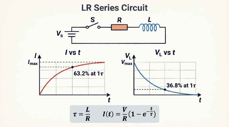
LR Series Circuit: Complete Guide to Transient Response, Time Constant, and AC Analysis
Introduction to the LR Series Circuit
An LR series circuit (also known as an RL circuit) is one of the most fundamental building blocks in electrical engineering. It consists of a resistor ($R$) and an inductor ($L$) connected in series with a voltage source. While it may seem like a simple combination of two passive components, the interaction between the resistor’s energy dissipation and the inductor’s energy storage creates fascinating and highly useful electrical behavior.
The defining characteristic of an LR circuit is its transient response. Unlike a purely resistive circuit where current changes instantaneously when a switch is flipped, an LR circuit resists sudden changes in current due to the inductor’s “electrical inertia.” When a DC voltage is applied, the current does not jump to its maximum value instantly; instead, it rises exponentially over time. Similarly, when the voltage is removed, the current decays exponentially rather than dropping to zero immediately.
Understanding the LR series circuit is critical for designing timing circuits, relay delays, motor starters, power supply filters, and snubber networks. Furthermore, analyzing this circuit in an AC steady-state introduces the foundational concepts of impedance and phase shift. This comprehensive guide will explore the DC transient response, the time constant, AC steady-state analysis, and practical applications of the LR series circuit.
What is an LR Series Circuit?
An LR series circuit is an electrical circuit containing a resistor and an inductor connected in series. Its defining characteristic is that it opposes sudden changes in current, causing the current to rise or decay exponentially over time rather than instantaneously. This behavior is governed by the circuit’s time constant ($\tau = L/R$).
The Physics of the DC Transient Response
To understand the LR circuit, let’s analyze what happens when a DC voltage source ($V$) is suddenly connected to a series resistor and inductor by closing a switch at time $t = 0$.
The Moment the Switch Closes ($t = 0$)
At the exact instant the switch closes, the current tries to jump from 0 Amps to its maximum value. However, the inductor fiercely opposes this sudden change. According to Lenz’s Law, the changing current generates a rapidly expanding magnetic field, which induces a back EMF (counter-electromotive force) in the inductor.
At $t = 0$, this back EMF is exactly equal and opposite to the applied source voltage ($V_L = -V$). Because the inductor’s voltage cancels the source voltage, the voltage across the resistor is zero, and therefore, the initial current is zero. The inductor initially acts like an open circuit.
The Transient Period ($t > 0$)
As time progresses, the current begins to flow and increase. Because the current is rising more slowly, the rate of change of current ($di/dt$) decreases. Consequently, the back EMF induced by the inductor decreases.
As the inductor’s voltage drops, more of the source voltage is applied across the resistor, allowing the current to increase further. This creates a continuous feedback loop: as current increases, the rate of increase slows down, causing the inductor’s opposing voltage to gradually fade away. The current follows an exponential growth curve.
The Steady State ($t \to \infty$)
Eventually, the current reaches a point where it is no longer changing ($di/dt = 0$). When the current is constant, the magnetic field is static, and the inductor induces zero back EMF. At this point, the inductor acts as a short circuit (a simple piece of wire). The only opposition to current flow is the resistor.
The maximum steady-state current is determined purely by Ohm’s Law:
$I_{max} = \frac{V}{R}$
The Time Constant ($\tau$)
The speed at which the current rises or decays in an LR circuit is determined by a single, crucial parameter: the Time Constant, denoted by the Greek letter tau ($\tau$).
The time constant is defined as the ratio of the inductance to the resistance:
$\tau = \frac{L}{R}$
Where:
- $\tau$ = Time constant in seconds (s)
- $L$ = Inductance in Henrys (H)
- $R$ = Resistance in Ohms ($\Omega$)
The 63.2% Rule
The time constant has a very specific physical meaning: It is the time it takes for the current to reach approximately 63.2% of its final maximum steady-state value during charging, or to decay to 36.8% of its initial value during discharge.
- After $1\tau$: Current reaches 63.2% of $I_{max}$
- After $2\tau$: Current reaches 86.5% of $I_{max}$
- After $3\tau$: Current reaches 95.0% of $I_{max}$
- After $4\tau$: Current reaches 98.2% of $I_{max}$
- After $5\tau$: Current reaches 99.3% of $I_{max}$
In practical engineering, a circuit is considered to have reached steady state after 5 time constants ($5\tau$), as the remaining change is negligible.
What is the time constant of an LR circuit?
The time constant ($\tau$) of an LR circuit is calculated as $\tau = L/R$. It represents the time required for the current to reach 63.2% of its maximum steady-state value. After 5 time constants ($5\tau$), the circuit is considered to have reached steady state.
Mathematical Equations for Transient Response
To precisely calculate the voltage and current at any given moment during the transient period, we use exponential equations derived from solving the circuit’s differential equation.
1. Current Growth (Charging)
When voltage is applied, the current $i(t)$ at any time $t$ is:
$i(t) = \frac{V}{R} \left(1 – e^{-t/\tau}\right)$
2. Voltage Across the Resistor
Since $v_R(t) = i(t) \times R$, the resistor voltage follows the same curve as the current:
$v_R(t) = V \left(1 – e^{-t/\tau}\right)$
3. Voltage Across the Inductor
The inductor voltage starts at the maximum source voltage $V$ and decays exponentially to zero:
$v_L(t) = V e^{-t/\tau}$
(Note: $e$ is Euler’s number, approximately 2.71828)
Practical Calculation Example: DC Transient
Problem: An LR series circuit consists of a 12V DC source, a resistor $R = 100 \Omega$, and an inductor $L = 50 \text{ mH}$ (0.05 H). Calculate:
- The time constant ($\tau$).
- The steady-state maximum current ($I_{max}$).
- The current flowing through the circuit at $t = 1 \text{ ms}$ (0.001 s).
Solution:
Step 1: Calculate Time Constant
$\tau = \frac{L}{R} = \frac{0.05}{100} = 0.0005 \text{ s} = \mathbf{0.5 \text{ ms}}$
Step 2: Calculate Maximum Current
$I_{max} = \frac{V}{R} = \frac{12}{100} = \mathbf{0.12 \text{ A}} \text{ (or 120 mA)}$
Step 3: Calculate Current at $t = 1 \text{ ms}$
Note that $t = 1 \text{ ms}$ is exactly $2\tau$ ($2 \times 0.5 \text{ ms}$).
$i(0.001) = 0.12 \left(1 – e^{-0.001 / 0.0005}\right)$
$i(0.001) = 0.12 \left(1 – e^{-2}\right)$
$i(0.001) = 0.12 \left(1 – 0.1353\right)$
$i(0.001) = 0.12 \times 0.8647$
$i(0.001) \approx 0.1038 \text{ A} \text{ (or 103.8 mA)}$
Verification: At $2\tau$, the current should be roughly 86.5% of $I_{max}$. $0.12 \times 0.865 = 0.1038 \text{ A}$. The math checks out perfectly.
LR Series Circuit in AC Steady-State
While the transient response describes the circuit’s behavior during the first few milliseconds after a switch is flipped, the AC steady-state describes how the circuit behaves when driven by a continuous sinusoidal AC voltage.
In an AC circuit, the inductor never reaches a “steady” DC current. Instead, it continuously opposes the alternating current, presenting a frequency-dependent opposition called inductive reactance ($X_L$).
Calculating AC Impedance ($Z$)
In an AC LR circuit, the total opposition to current is the impedance ($Z$), which is the phasor sum of resistance ($R$) and inductive reactance ($X_L = 2\pi f L$). Because the voltage across the resistor is in phase with the current, and the voltage across the inductor leads the current by 90°, they form a right-angled Impedance Triangle.
$Z = \sqrt{R^2 + X_L^2}$
Phase Angle ($\theta$)
The current in an LR circuit always lags behind the source voltage. The phase angle $\theta$ is calculated as:
$\theta = \arctan\left(\frac{X_L}{R}\right)$
Practical Calculation Example: AC Steady-State
Problem: An LR series circuit is connected to a 120V (RMS), 60 Hz AC source. The resistor is $30 \Omega$ and the inductor is $0.1 \text{ H}$. Calculate the impedance, total current, and phase angle.
Solution:
Step 1: Calculate Inductive Reactance
$X_L = 2\pi f L = 2 \times 3.1416 \times 60 \times 0.1 = \mathbf{37.7 \Omega}$
Step 2: Calculate Total Impedance
$Z = \sqrt{R^2 + X_L^2} = \sqrt{30^2 + 37.7^2} = \sqrt{900 + 1421.3} = \sqrt{2321.3}$
$Z \approx 48.18 \Omega$
Step 3: Calculate Total RMS Current
$I = \frac{V}{Z} = \frac{120}{48.18} \approx \mathbf{2.49 \text{ A}}$
Step 4: Calculate Phase Angle
$\theta = \arctan\left(\frac{37.7}{30}\right) = \arctan(1.257) \approx \mathbf{51.5^\circ}$
Result: The circuit draws 2.49 Amps, and the current lags the source voltage by 51.5 degrees.
Practical Applications of LR Circuits
The unique time-delay and frequency-dependent characteristics of the LR circuit make it invaluable in numerous real-world applications.
1. Relay and Contactor Delay Circuits
When a relay coil (which is essentially an inductor with inherent resistance) is energized, the LR time constant causes the current to rise gradually. This introduces a slight, predictable delay before the magnetic field is strong enough to pull in the relay contacts. Engineers can add external resistors or inductors to precisely tune this turn-on delay.
2. Snubber Circuits
When a switch opens in a circuit containing an inductor (like a motor or relay coil), the sudden collapse of the magnetic field ($di/dt$ is huge and negative) induces a massive voltage spike ($V = L \cdot di/dt$). This spike can arc across switch contacts or destroy semiconductor transistors. A snubber circuit (often an LR or RC network placed in parallel with the switch or inductor) provides a safe path for the inductor’s stored energy to dissipate gradually, protecting the components.
3. Passive Filters
LR circuits act as frequency-dependent voltage dividers.
- LR Low-Pass Filter: If the output is taken across the resistor, high frequencies are blocked (because $X_L$ is high) and low frequencies pass through.
- LR High-Pass Filter: If the output is taken across the inductor, low frequencies are blocked (because $X_L$ is low, acting like a short) and high frequencies pass through.
4. Motor Starting
Large AC induction motors draw massive inrush currents when first started. Series LR reactors are sometimes temporarily placed in series with the motor windings to limit the initial rate of current rise, reducing mechanical stress on the motor and preventing voltage dips on the power line.
The LR series circuit beautifully demonstrates the dynamic interplay between energy dissipation (resistance) and energy storage (inductance). Whether analyzing the exponential transient response of a DC circuit or calculating the impedance and phase shift of an AC circuit, the LR combination is a cornerstone of electrical theory.
Key takeaways from this guide include:
- Electrical Inertia: Inductors oppose sudden changes in current, causing exponential growth or decay rather than instantaneous jumps.
- Time Constant ($\tau$): Defined as $\tau = L/R$. It is the time required for the current to reach 63.2% of its maximum value. Steady state is reached at $5\tau$.
- Transient Equations: Current grows as $i(t) = \frac{V}{R}(1 – e^{-t/\tau})$, while inductor voltage decays as $v_L(t) = V e^{-t/\tau}$.
- AC Steady-State: In AC, the circuit exhibits impedance $Z = \sqrt{R^2 + X_L^2}$, and the current always lags the voltage by an angle $\theta = \arctan(X_L/R)$.
- Applications: LR circuits are essential for timing delays, snubber protection, passive filtering, and motor control.
Mastering the LR series circuit provides the essential foundation for understanding more complex RLC networks, transient analysis, and AC power systems. In our next article, we will explore the specific phenomenon of Inductive Reactance in greater depth, examining how frequency fundamentally alters an inductor’s behavior in AC systems.