Synchronous Counter
Synchronous Counter: Complete Guide to High-Speed Digital Counter Design
Introduction to Synchronous Counters
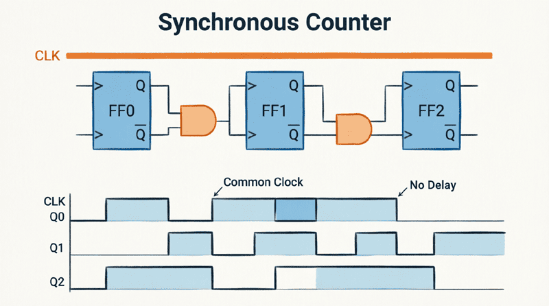
Synchronous counters represent a significant advancement over their asynchronous counterparts. While asynchronous (ripple) counters suffer from cumulative propagation delays that limit their speed, synchronous counters solve this problem by clocking all flip-flops simultaneously with a common clock signal.
A synchronous counter is a sequential logic circuit where all flip-flops receive the same clock pulse at exactly the same time. This parallel clocking ensures that all output bits change state simultaneously (or nearly so), eliminating the “ripple” effect and its associated timing problems. This makes synchronous counters ideal for high-speed applications where timing precision and maximum operating frequency are critical.
Synchronous counters are the backbone of modern digital systems, found in:
- Microprocessors: Program counters and instruction sequencers
- Digital Signal Processing: Sample counters and address generators
- Communication Systems: Frame counters and protocol state machines
- High-Speed Data Acquisition: Timing and control circuits
- Computer Architecture: Memory address counters and cache controllers
This comprehensive guide will explore the architecture, design methodology, and advantages of synchronous counters. We will examine how to design synchronous up and down counters, analyze their timing characteristics, and compare them with asynchronous designs to understand when each type is most appropriate.
What is a Synchronous Counter?
A synchronous counter is a digital circuit where all flip-flops are triggered simultaneously by a common clock signal. Unlike asynchronous counters, the clock is applied in parallel to all stages, eliminating cumulative propagation delay and allowing for much higher operating frequencies. All output bits change state at the same time.
How Synchronous Counters Work
Parallel Clocking Architecture
The fundamental difference between synchronous and asynchronous counters lies in the clock distribution:
Asynchronous Counter:
- Clock ripples through the chain
- FF0 clocks FF1, FF1 clocks FF2, etc.
- Total delay = n × t_pd
Synchronous Counter:
- External clock connects to ALL flip-flops simultaneously
- All flip-flops trigger on the same clock edge
- Total delay = 1 × t_pd (regardless of counter size)
This parallel clocking is the key to the synchronous counter’s superior performance.
The Toggle Logic Problem
While parallel clocking solves the timing problem, it introduces a new challenge: How do we make each flip-flop toggle at the correct time?
In a binary counter:
- The LSB (Q0) toggles on EVERY clock pulse
- Q1 toggles only when Q0 = 1 (every 2nd pulse)
- Q2 toggles only when Q0 = 1 AND Q1 = 1 (every 4th pulse)
- Q3 toggles only when Q0 = Q1 = Q2 = 1 (every 8th pulse)
In an asynchronous counter, this is handled automatically by the ripple effect. In a synchronous counter, we must use combinational logic (AND gates) to control when each flip-flop should toggle.
Using T Flip-Flops or JK Flip-Flops
Synchronous counters typically use T (Toggle) flip-flops or JK flip-flops configured in toggle mode. The T or JK inputs are controlled by logic gates that determine whether the flip-flop should toggle or hold its current state.
Toggle Condition:
- If T = 1 (or J = K = 1): Flip-flop toggles on clock edge
- If T = 0 (or J = K = 0): Flip-flop holds its state
The logic gates generate the appropriate T inputs based on the current state of the counter outputs.
Why do synchronous counters need additional logic gates?
Synchronous counters need AND gates to control when each flip-flop should toggle. Since all flip-flops receive the clock simultaneously, we must use logic to ensure that Q1 only toggles when Q0=1, Q2 only toggles when Q0=Q1=1, and so on. This logic replaces the automatic ripple triggering of asynchronous counters.
Designing Synchronous Up Counters
Design Methodology
Designing a synchronous up counter follows a systematic approach:
Step 1: Determine the Number of Flip-Flops
For a MOD-N counter, you need n flip-flops where $2^n \geq N$.
- MOD-8 counter: 3 flip-flops ($2^3 = 8$)
- MOD-16 counter: 4 flip-flops ($2^4 = 16$)
Step 2: Connect the Clock
Connect the external clock signal to the CLK input of ALL flip-flops in parallel.
Step 3: Design the Toggle Logic
- FF0 (LSB): T0 = 1 (always toggle)
- FF1: T1 = Q0 (toggle when Q0 = 1)
- FF2: T2 = Q0 · Q1 (toggle when Q0 AND Q1 = 1)
- FF3: T3 = Q0 · Q1 · Q2 (toggle when Q0 AND Q1 AND Q2 = 1)
Step 4: Implement with AND Gates
Use AND gates to generate the toggle signals for each flip-flop based on the outputs of the preceding flip-flops.
4-Bit Synchronous Up Counter Example
Let’s design a 4-bit synchronous binary up counter (MOD-16):
Circuit Configuration:
- 4 JK flip-flops (FF0, FF1, FF2, FF3)
- All J and K inputs controlled by toggle logic
- Common clock to all CLK inputs
Toggle Logic Equations:
- J0 = K0 = 1 (FF0 always toggles)
- J1 = K1 = Q0 (FF1 toggles when Q0 = 1)
- J2 = K2 = Q0 · Q1 (FF2 toggles when Q0 = Q1 = 1)
- J3 = K3 = Q0 · Q1 · Q2 (FF3 toggles when Q0 = Q1 = Q2 = 1)
Implementation:
- FF0: J and K tied to VCC (logic 1)
- FF1: J and K connected to Q0
- FF2: J and K connected to output of AND gate (inputs: Q0, Q1)
- FF3: J and K connected to output of AND gate (inputs: Q0, Q1, Q2)
Count Sequence:
0000 → 0001 → 0010 → 0011 → 0100 → 0101 → 0110 → 0111 → 1000 → 1001 → 1010 → 1011 → 1100 → 1101 → 1110 → 1111 → 0000 (repeat)
Designing Synchronous Down Counters
Synchronous down counters count in reverse: 1111 → 1110 → 1101 → … → 0000.
Toggle Logic for Down Counters
The toggle conditions for a down counter are different from an up counter:
- FF0 (LSB): T0 = 1 (always toggle)
- FF1: T1 = $\overline{Q_0}$ (toggle when Q0 = 0)
- FF2: T2 = $\overline{Q_0} \cdot \overline{Q_1}$ (toggle when Q0 = Q1 = 0)
- FF3: T3 = $\overline{Q_0} \cdot \overline{Q_1} \cdot \overline{Q_2}$ (toggle when Q0 = Q1 = Q2 = 0)
Implementation:
Instead of using the Q outputs to control the AND gates, we use the $\overline{Q}$ (inverted) outputs.
Toggle Logic Equations:
- J0 = K0 = 1
- J1 = K1 = $\overline{Q_0}$
- J2 = K2 = $\overline{Q_0} \cdot \overline{Q_1}$
- J3 = K3 = $\overline{Q_0} \cdot \overline{Q_1} \cdot \overline{Q_2}$
Synchronous Up/Down Counters
A synchronous up/down counter can count in either direction based on a control signal.
Design Approach
Control Signal:
- UP/DOWN = 1: Count UP
- UP/DOWN = 0: Count DOWN
Toggle Logic:
We combine the up and down logic using multiplexers or AND-OR logic:
For FF1:
- Up condition: Q0
- Down condition: $\overline{Q_0}$
- Combined: T1 = (UP · Q0) + (DOWN · $\overline{Q_0}$)
For FF2:
- Up condition: Q0 · Q1
- Down condition: $\overline{Q_0} \cdot \overline{Q_1}$
- Combined: T2 = (UP · Q0 · Q1) + (DOWN · $\overline{Q_0} \cdot \overline{Q_1}$)
This pattern continues for higher-order bits.
Implementation
Use AND-OR gates or 2-to-1 multiplexers to select between the up and down toggle conditions based on the UP/DOWN control signal.
Timing Analysis and Advantages
Elimination of Cumulative Delay
The primary advantage of synchronous counters is the elimination of cumulative propagation delay.
Asynchronous Counter Delay:
$t_{pd(total)} = n \times t_{pd}$
Synchronous Counter Delay:
$t_{pd(total)} = t_{pd(FF)} + t_{pd(AND_gate)}$
Where:
- $t_{pd(FF)}$ = Propagation delay of one flip-flop
- $t_{pd(AND_gate)}$ = Propagation delay of the AND gate logic
Key Insight: The total delay is CONSTANT regardless of the number of flip-flops!
Example Timing Comparison
Scenario: 4-bit counter using flip-flops with $t_{pd} = 20\text{ ns}$ and AND gates with $t_{pd} = 10\text{ ns}$.
Asynchronous Counter:
$t_{pd(total)} = 4 \times 20\text{ ns} = 80\text{ ns}$
$f_{max} = \frac{1}{80\text{ ns}} = 12.5\text{ MHz}$
Synchronous Counter:
$t_{pd(total)} = 20\text{ ns (FF)} + 10\text{ ns (AND)} = 30\text{ ns}$
$f_{max} = \frac{1}{30\text{ ns}} = 33.3\text{ MHz}$
Result: The synchronous counter is nearly 3× faster!
Simultaneous State Changes
In a synchronous counter, all output bits change at nearly the same time (within the propagation delay of the flip-flops). This eliminates:
- Decoding glitches
- Intermediate false states
- Timing uncertainty
This makes synchronous counters ideal for applications requiring precise timing and glitch-free operation.
What is the maximum frequency advantage of synchronous counters?
Synchronous counters can operate at much higher frequencies because the total propagation delay is constant (one flip-flop delay plus gate delay) regardless of counter size. An asynchronous counter’s delay increases with each added flip-flop, severely limiting its maximum frequency.
Practical Design Examples
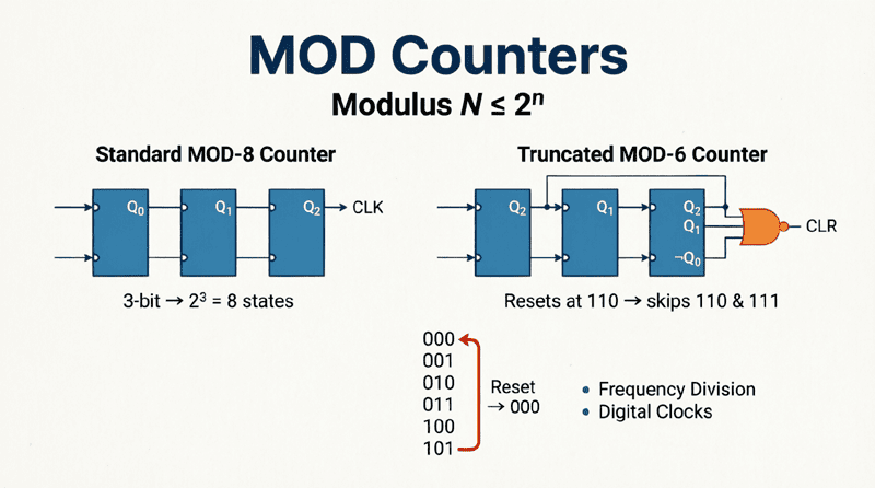
Example 1: MOD-6 Synchronous Counter
Problem: Design a synchronous counter that counts from 0 to 5 (MOD-6) and then resets.
Solution:
Step 1: Determine Flip-Flops
Need 3 flip-flops (MOD-8 natural count, will modify to MOD-6)
Step 2: Standard Synchronous Up Counter Logic
- J0 = K0 = 1
- J1 = K1 = Q0
- J2 = K2 = Q0 · Q1
Step 3: Add Reset Logic
We need to reset when the count reaches 6 (binary 110).
- Use an AND gate to detect state 110 (Q2=1, Q1=1, Q0=0)
- Connect AND gate output to CLEAR (reset) inputs of all flip-flops
- When count = 110, AND gate outputs HIGH, resetting all FFs to 000
Step 4: Count Sequence
000 → 001 → 010 → 011 → 100 → 101 → 000 (reset)
Example 2: Calculating Maximum Frequency
Problem: A 6-bit synchronous counter uses flip-flops with $t_{pd} = 15\text{ ns}$ and AND gates with $t_{pd} = 8\text{ ns}$. Calculate the maximum clock frequency.
Solution:
Total Propagation Delay:
$t_{pd(total)} = t_{pd(FF)} + t_{pd(AND)}$
$t_{pd(total)} = 15\text{ ns} + 8\text{ ns} = 23\text{ ns}$
Note: The delay is independent of the 6-bit size!
Maximum Frequency:
$f_{max} = \frac{1}{t_{pd(total)}} = \frac{1}{23 \times 10^{-9}}$
$f_{max} = 43.5\text{ MHz}$
Comparison with Asynchronous:
If this were an asynchronous counter:
$t_{pd(total)} = 6 \times 15\text{ ns} = 90\text{ ns}$
$f_{max} = 11.1\text{ MHz}$
The synchronous design is nearly 4× faster!
Advantages and Disadvantages
Advantages of Synchronous Counters
- High Speed:
- Constant propagation delay regardless of counter size
- Much higher maximum operating frequency
- Ideal for high-speed digital systems
- No Decoding Glitches:
- All bits change simultaneously
- No intermediate false states
- Clean, glitch-free outputs
- Predictable Timing:
- Precise control over state transitions
- Easier to analyze and verify
- Suitable for synchronous system design
- Scalability:
- Can easily add more bits without speed penalty
- Modular design approach
Disadvantages of Synchronous Counters
- Complexity:
- Requires additional logic gates (AND gates)
- More wiring and interconnections
- More complex design process
- Component Count:
- More ICs required for the same MOD number
- Higher cost for simple applications
- More power consumption
- Design Effort:
- Requires careful logic design
- More difficult to troubleshoot
- Not as intuitive as ripple counters
Synchronous vs. Asynchronous: When to Use Which
Use Synchronous Counters When:
- High speed is critical (MHz range operation)
- Glitch-free operation is required (decoding applications)
- Precise timing is needed (synchronous systems)
- Large counters are needed (8-bit, 16-bit, etc.)
- System uses a global clock (microprocessor-based systems)
Use Asynchronous Counters When:
- Simplicity is preferred (educational projects, prototypes)
- Low speed is acceptable (kHz range, human-interface timing)
- Component count must be minimized (cost-sensitive designs)
- Frequency division is the primary goal (not counting)
- Power consumption is critical (fewer gates = less power)
Advanced Topics: Carry Look-Ahead
For very large synchronous counters (e.g., 16-bit, 32-bit), the AND gates required for the toggle logic can become very large (many inputs), which introduces its own delay.
Solution: Carry Look-Ahead Logic
Instead of using a single large AND gate, use a hierarchical structure:
- Generate “carry” signals in stages
- Use smaller, faster gates
- Similar to carry look-ahead adders in arithmetic circuits
This technique further improves the speed of very large synchronous counters.
Synchronous counters represent a significant advancement in digital counter design, offering superior speed and reliability compared to asynchronous (ripple) counters. By clocking all flip-flops simultaneously and using combinational logic to control toggle conditions, synchronous counters eliminate the cumulative propagation delay that limits asynchronous designs.
Key takeaways from this guide include:
- Parallel Clocking: All flip-flops receive the clock simultaneously, ensuring simultaneous state changes.
- Toggle Logic: AND gates control when each flip-flop should toggle based on the states of preceding flip-flops.
- Speed Advantage: Total propagation delay is constant (one FF delay + gate delay) regardless of counter size, enabling much higher operating frequencies.
- Design Flexibility: Can be easily configured for up, down, or up/down counting, and modified for custom MOD numbers.
- Glitch-Free Operation: Simultaneous state changes eliminate decoding glitches and intermediate false states.
- Trade-offs: Higher speed and reliability come at the cost of increased complexity and component count.
Understanding synchronous counters is essential for designing modern high-speed digital systems. While they require more design effort than asynchronous counters, their superior performance makes them the standard choice for virtually all professional digital electronics applications, from microprocessors to communication systems.
As you progress in digital design, you’ll find that the principles learned here—parallel clocking, synchronous design, and timing analysis—apply far beyond counters to all sequential logic circuits, forming the foundation of reliable, high-performance digital systems.