MOD Counters
MOD Counters: Complete Guide to Custom Modulus Counter Design
Introduction to MOD Counters
In digital electronics, the term MOD (short for modulus) refers to the number of distinct states a counter cycles through before repeating. While standard binary counters naturally count in powers of 2 (MOD-2, MOD-4, MOD-8, MOD-16), many real-world applications require counters with custom modulus values like MOD-5, MOD-6, MOD-10, MOD-12, or any arbitrary number N.
A MOD-N counter is a sequential logic circuit that counts through exactly N unique states before resetting to its initial state and repeating the sequence. For example:
- MOD-6 counter: Counts 0, 1, 2, 3, 4, 5, then resets to 0
- MOD-10 counter: Counts 0-9 (also called a decade or BCD counter)
- MOD-12 counter: Counts 0-11 (useful for digital clocks showing hours)
MOD counters are fundamental building blocks in countless digital systems:
- Digital Clocks: MOD-6 for seconds/minutes (0-5), MOD-12 for hours (1-12)
- Frequency Dividers: Creating specific division ratios (÷5, ÷7, ÷12)
- Control Systems: Sequencing through specific operational states
- Timers: Counting specific time intervals
- State Machines: Implementing custom control sequences
This comprehensive guide will explore the theory, design methodologies, and practical implementation of MOD counters with various modulus values. We will examine different design techniques including reset logic, preset methods, and the use of dedicated counter ICs, providing you with the knowledge to design custom MOD counters for any application.
What is a MOD Counter?
A MOD-N counter is a digital circuit that counts through exactly N distinct states before resetting. For example, a MOD-6 counter cycles through states 0-1-2-3-4-5-0. MOD counters can be designed using flip-flops with reset logic, preset methods, or dedicated ICs to achieve any desired counting sequence.
Understanding Counter Modulus
What is Modulus?
The modulus of a counter is the total number of unique states it passes through in one complete counting cycle before returning to the initial state. It’s essentially the “length” of the counting sequence.
Mathematical Definition:
For a counter with n flip-flops:
- Maximum MOD: $2^n$ (full binary counter)
- Custom MOD: Any value from 2 to $2^n$
Examples:
- 2 flip-flops: Maximum MOD-4 (00, 01, 10, 11)
- 3 flip-flops: Maximum MOD-8 (000 to 111)
- 4 flip-flops: Maximum MOD-16 (0000 to 1111)
Natural vs. Truncated Counters
Natural (Full-Sequence) Counters:
These counters use all possible states of the flip-flops:
- MOD-2, MOD-4, MOD-8, MOD-16, etc.
- No additional logic required
- Simple design
Truncated (Custom MOD) Counters:
These counters skip some states to achieve a specific modulus:
- MOD-3, MOD-5, MOD-6, MOD-10, MOD-12, etc.
- Require additional logic (reset or preset)
- More complex design
Calculating Required Flip-Flops
To design a MOD-N counter, you need to determine the minimum number of flip-flops required:
Formula:
$$n \geq \log_2(N)$$
Where:
- $n$ = Number of flip-flops
- $N$ = Desired MOD value
Examples:
- MOD-6 counter: $\log_2(6) = 2.58$, so $n = 3$ flip-flops needed
- MOD-10 counter: $\log_2(10) = 3.32$, so $n = 4$ flip-flops needed
- MOD-12 counter: $\log_2(12) = 3.58$, so $n = 4$ flip-flops needed
Key Insight: You always round up to the next whole number because you can’t have a fraction of a flip-flop!
How many flip-flops are needed for a MOD-10 counter?
A MOD-10 counter requires 4 flip-flops because $\log_2(10) = 3.32$, which rounds up to 4. With 4 flip-flops, you can create counters from MOD-2 to MOD-16. The extra states (10-15) are skipped using reset logic.
Design Methods for MOD Counters
There are several techniques to create custom MOD counters. The choice depends on the specific MOD value, available components, and design requirements.
Method 1: Reset (Clear) Method
The reset method is the most common and straightforward approach for creating MOD counters. It works by detecting when the counter reaches the undesired state and immediately resetting it to zero.
Design Process:
- Determine the number of flip-flops:
Calculate $n = \lceil \log_2(N) \rceil$ - Identify the reset state:
The counter should reset when it reaches state N (not N-1) - Create reset detection logic:
Use an AND gate to detect the binary value of state N - Connect to CLEAR inputs:
Connect the AND gate output to the asynchronous CLEAR (reset) inputs of all flip-flops
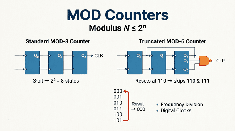
Example: MOD-6 Counter Design
Step 1: Flip-Flops Required
$n = \lceil \log_2(6) \rceil = \lceil 2.58 \rceil = 3$ flip-flops
Step 2: Count Sequence
Desired: 000, 001, 010, 011, 100, 101, (then reset)
Reset when: 110 (decimal 6)
Step 3: Reset Detection
State 110 means:
- Q2 = 1 (MSB)
- Q1 = 1
- Q0 = 0 (LSB)
Simplified Logic:
Since 110 is the first state where both Q2 and Q1 are HIGH, we can use:
Reset = Q2 · Q1 (2-input AND gate)
Step 4: Circuit Implementation
- 3 JK or D flip-flops in binary counter configuration
- 2-input AND gate with inputs Q2 and Q1
- AND gate output to CLEAR pins of all flip-flops
- When count reaches 110, immediate reset to 000
Timing Note:
The reset is asynchronous, so state 110 exists only momentarily (for a few nanoseconds) before resetting to 000. This creates a very brief glitch that is usually acceptable for most applications.
Method 2: Preset (Load) Method
The preset method loads a specific starting value into the counter when it reaches the terminal count. This is useful for counters that don’t start from zero.
Design Process:
- Determine start and end values:
Define the counting range (e.g., 3 to 9 for MOD-7) - Detect terminal count:
Create logic to detect when the counter reaches the end value - Load start value:
When terminal count is detected, load the start value on the next clock
Example: MOD-5 Counter (Counting 3-7)
Count Sequence:
011 (3), 100 (4), 101 (5), 110 (6), 111 (7), then back to 011 (3)
Implementation:
- Detect state 111 (Q2·Q1·Q0)
- Use LOAD input to load 011 on next clock
- Requires synchronous load capability
Advantages of Preset Method:
- Can start from any value
- Synchronous operation (no glitches)
- Better for high-speed applications
Disadvantages:
- More complex logic
- Requires presettable flip-flops or ICs
Method 3: Using Dedicated MOD Counter ICs
Several integrated circuits are designed specifically for common MOD values, eliminating the need for external reset logic.
Popular MOD Counter ICs:
74LS90 / 74HC90:
- MOD-10 (decade) counter
- Can be configured as MOD-2, MOD-5, or MOD-10
74LS92 / 74HC92:
- MOD-12 counter
- Divide-by-12 frequency divider
- Ideal for digital clock hours
74LS93 / 74HC93:
- MOD-16 counter (4-bit binary)
- Can be configured as MOD-2, MOD-8, or MOD-16
- Can create custom MOD using reset method
4029:
- Presettable binary/BCD counter
- Can be configured for any MOD up to 16
- Up/down counting capability
Common MOD Counter Designs
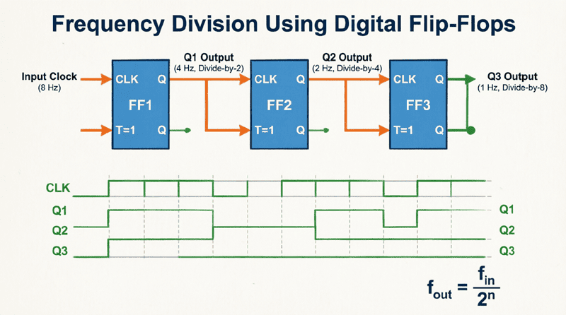
MOD-2 Counter (Divide-by-2)
The simplest counter, using just one flip-flop.
Circuit:
- Single T or JK flip-flop
- T = 1 (or J = K = 1)
- Output toggles on each clock
- Frequency division: $f_{out} = f_{in} / 2$
Applications:
- Basic frequency division
- Square wave generation
- Simple toggle circuits
MOD-4 Counter (Divide-by-4)
Uses two flip-flops to count 00, 01, 10, 11.
Circuit:
- 2 flip-flops in cascade
- Natural binary counter
- No reset logic needed
Count Sequence:
00 → 01 → 10 → 11 → 00
Frequency Division:
- Q0: $f_{in} / 2$
- Q1: $f_{in} / 4$
MOD-5 Counter
Requires 3 flip-flops ($\lceil \log_2(5) \rceil = 3$).
Design Using Reset Method:
Count Sequence:
000, 001, 010, 011, 100, (reset)
Reset Detection:
Reset when count = 101 (decimal 5)
- Q2 = 1
- Q1 = 0
- Q0 = 1
Logic:
Reset = Q2 · Q0 (AND gate)
Circuit:
- 3 flip-flops
- 2-input AND gate (Q2 and Q0)
- AND output to CLEAR pins
MOD-6 Counter
Already covered in detail earlier, but worth summarizing:
Flip-Flops: 3
Reset State: 110 (decimal 6)
Reset Logic: Q2 · Q1
Applications: Digital clock seconds/minutes (0-5)
MOD-8 Counter
Natural binary counter with 3 flip-flops.
Circuit:
- 3 flip-flops
- No reset logic needed
- Counts 000 to 111
Frequency Division:
- Q0: ÷2
- Q1: ÷4
- Q2: ÷8
MOD-10 Counter (Decade/BCD)
Covered extensively in Article 6. Key points:
Flip-Flops: 4
Reset State: 1010 (decimal 10)
Reset Logic: Q3 · Q1
IC: 74LS90
Applications: Decimal counting, digital displays
MOD-12 Counter
Essential for digital clocks showing hours (1-12 or 0-11).
Design Using Reset Method:
Flip-Flops: 4 ($\lceil \log_2(12) \rceil = 4$)
Count Sequence:
0000, 0001, …, 1011, (reset)
Reset State:
1100 (decimal 12)
Reset Logic:
Reset = Q3 · Q2 (AND gate)
Alternative: Using 74LS92
The 74LS92 is a dedicated MOD-12 counter IC:
- Built-in divide-by-12 functionality
- No external reset logic needed
- Ideal for clock applications
74LS92 Configuration:
- Contains divide-by-2 and divide-by-6 sections
- Connect Q0 to CLK B for MOD-12
- Outputs: Q0, Q1, Q2, Q3
MOD-16 Counter
Natural binary counter with 4 flip-flops.
Circuit:
- 4 flip-flops
- No reset logic
- Counts 0000 to 1111
IC: 74LS93 (4-bit binary counter)
Applications:
- Full binary counting
- Address generation
- Maximum utilization of flip-flops
Advanced MOD Counter Techniques
Cascading MOD Counters
To create large MOD values, you can cascade smaller MOD counters.
Example: MOD-60 Counter (for seconds/minutes)
Approach 1: MOD-6 + MOD-10
- First counter: MOD-6 (0-5)
- Second counter: MOD-10 (0-9)
- Cascade: MOD-6 × MOD-10 = MOD-60
- Count sequence: 00, 01, …, 59, 00
Circuit:
- 74LS90 configured as MOD-6 (units of seconds)
- 74LS90 configured as MOD-10 (tens of seconds)
- Carry from MOD-6 clocks MOD-10
Approach 2: MOD-2 + MOD-3 + MOD-10
- Even more modular design
- Useful for complex timing systems
Frequency Division with MOD Counters
Every MOD-N counter is also a divide-by-N frequency divider.
Formula:
$$f_{out} = \frac{f_{in}}{N}$$
Example:
- Input: 1 MHz clock
- MOD-10 counter
- Output: 100 kHz
Applications:
- Clock generation
- Baud rate generation
- Audio frequency synthesis
- Timer bases
Programmable MOD Counters
For applications requiring variable MOD values, use presettable counters like the 74LS191 or 74LS193.
Operation:
- Load initial value
- Count to terminal value
- Detect terminal count
- Reload initial value
- Repeat
MOD Calculation:
$$N = \text{Terminal Count} – \text{Initial Value} + 1$$
Example:
- Initial value: 0100 (4)
- Terminal value: 1011 (11)
- MOD = 11 – 4 + 1 = 8
Practical Applications of MOD Counters
1. Digital Clock Design
A complete digital clock requires multiple MOD counters:
Seconds:
- Units: MOD-10 counter (0-9)
- Tens: MOD-6 counter (0-5)
- Combined: MOD-60 (00-59)
Minutes:
- Same as seconds: MOD-60
Hours:
- 12-hour format: MOD-12 (1-12)
- 24-hour format: MOD-24 (0-23)
Complete System:
- 6 BCD counters for HH:MM:SS display
- Cascaded with proper carry logic
- Each digit drives a 7-segment display
2. Frequency Synthesis
MOD counters create precise frequency division ratios:
Example: Radio Receiver
- Crystal oscillator: 10.24 MHz
- MOD-1024 counter
- Output: 10 kHz reference
- Used for channel selection
3. Traffic Light Controller
A traffic light sequence uses a MOD counter to cycle through states:
Sequence:
- State 0-3: Green (4 seconds)
- State 4-5: Yellow (2 seconds)
- State 6-9: Red (4 seconds)
- Total: MOD-10 counter
Implementation:
- MOD-10 counter
- Decoder logic for light control
- Clock: 1 Hz (1 second per state)
4. Washing Machine Timer
Washing machines use MOD counters for cycle timing:
Cycles:
- Wash: MOD-300 (5 minutes at 1 Hz)
- Rinse: MOD-180 (3 minutes)
- Spin: MOD-120 (2 minutes)
Design:
- Cascaded MOD counters
- Preset values for each cycle
- Automatic progression
5. Production Line Counter
Count products in batches:
Batch Counter:
- MOD-100 counter (count 100 items)
- When count reaches 100:
- Trigger packaging
- Reset counter
- Increment batch counter
Implementation:
- MOD-100 (two cascaded MOD-10)
- Reset detection at 100
- Output pulse for packaging
Design Examples and Calculations
Example 1: MOD-7 Counter Design
Problem: Design a MOD-7 counter using JK flip-flops and the reset method.
Solution:
Step 1: Determine Flip-Flops
$n = \lceil \log_2(7) \rceil = \lceil 2.81 \rceil = 3$ flip-flops
Step 2: Count Sequence
000, 001, 010, 011, 100, 101, 110, (reset)
Step 3: Reset State
Reset when count = 111 (decimal 7)
Step 4: Reset Logic
State 111: Q2 = 1, Q1 = 1, Q0 = 1
Logic Equation:
Reset = Q2 · Q1 · Q0 (3-input AND gate)
Step 5: Circuit
- 3 JK flip-flops in binary configuration
- 3-input AND gate
- AND output to CLEAR pins
- J = K = 1 for all flip-flops
Verification:
Count: 0→1→2→3→4→5→6→0 ✓
MOD = 7 ✓
Example 2: MOD-24 Counter for 24-Hour Clock
Problem: Design a MOD-24 counter for hours display in a 24-hour digital clock.
Solution:
Method 1: Single Counter
Flip-Flops:
$n = \lceil \log_2(24) \rceil = \lceil 4.58 \rceil = 5$ flip-flops
Reset State:
11000 (decimal 24)
Reset Logic:
Reset = Q4 · Q3 (AND gate)
Method 2: Cascaded Counters (Better)
Approach:
- Units: MOD-10 counter (0-9)
- Tens: MOD-3 counter (0-2) (but only counts 0, 1, 2)
- Combined: MOD-10 × MOD-3 = MOD-30, but we need MOD-24
Better Approach:
- Units: MOD-10 (0-9)
- Tens: MOD-2 (0-1) but with special reset
- When units = 0-3 and tens = 2, allow
- When units = 4-9 and tens = 2, reset
Complex Logic:
Actually, simpler to use:
- MOD-24 single counter with 5 flip-flops
- Reset at 11000 (24)
Example 3: Frequency Divider Chain
Problem: Create a frequency divider that converts 1 MHz to 100 Hz using MOD counters.
Solution:
Required Division:
$N = \frac{1,000,000}{100} = 10,000$
Approach 1: Single MOD-10000
- Requires 14 flip-flops ($\lceil \log_2(10000) \rceil = 14$)
- Complex reset logic
- Not practical
Approach 2: Cascaded Stages
Factorize 10,000:
$10,000 = 10 \times 10 \times 10 \times 10$
Implementation:
- Stage 1: MOD-10 (÷10) → 100 kHz
- Stage 2: MOD-10 (÷10) → 10 kHz
- Stage 3: MOD-10 (÷10) → 1 kHz
- Stage 4: MOD-10 (÷10) → 100 Hz
Components:
- 4 × 74LS90 ICs
- Each configured as MOD-10
- Cascade outputs to next stage clock
Advantages:
- Simple design
- Standard ICs
- Easy to troubleshoot
- Modular
Troubleshooting MOD Counters
Common Problems and Solutions
Problem 1: Counter Doesn’t Reset at Correct Value
Causes:
- Incorrect reset logic
- Loose connections
- Faulty AND gate
Solutions:
- Verify reset detection equation
- Check all connections with multimeter
- Test AND gate independently
- Ensure CLEAR pins are properly connected
Problem 2: Counter Skips States
Causes:
- Clock signal noise
- Switch bounce (if manual clock)
- Propagation delay issues
Solutions:
- Add debouncing circuit for manual clocks
- Use Schmitt trigger for clock input
- Add decoupling capacitors (0.1µF) near ICs
- Check for metastability
Problem 3: Glitches in Output
Causes:
- Asynchronous reset creates brief invalid states
- Race conditions in reset logic
Solutions:
- Use synchronous preset method instead
- Add output registers to capture stable values
- Use synchronous counters (74LS192/193)
- Accept glitches if they’re too brief to affect downstream circuits
Problem 4: Cascaded Counters Don’t Advance Properly
Causes:
- Incorrect carry connection
- Timing mismatch between stages
- Loading effects
Solutions:
- Verify carry/ripple connections
- Ensure proper edge triggering (rising vs. falling)
- Add buffer between stages if needed
- Check propagation delays
MOD counters are versatile digital circuits that count through a specific number of states before resetting. By understanding the principles of modulus, reset logic, and cascading techniques, you can design counters for any counting requirement.
Key takeaways from this guide include:
- Modulus Definition: A MOD-N counter cycles through exactly N unique states. The number of flip-flops required is $n = \lceil \log_2(N) \rceil$.
- Design Methods:
- Reset Method: Detect state N and asynchronously clear all flip-flops (simplest, most common)
- Preset Method: Load a start value when terminal count is reached (synchronous, glitch-free)
- Dedicated ICs: Use specialized ICs like 74LS90 (MOD-10), 74LS92 (MOD-12), or 74LS93 (MOD-16)
- Common MOD Values:
- MOD-2, MOD-4, MOD-8: Natural binary counters (no reset logic)
- MOD-6, MOD-10: Essential for digital clocks
- MOD-12: Hours display, frequency division
- MOD-16: Maximum utilization of 4 flip-flops
- Cascading: Combine smaller MOD counters to create larger modulus values (MOD-6 × MOD-10 = MOD-60).
- Frequency Division: Every MOD-N counter is also a divide-by-N frequency divider, making them essential for clock generation and timing applications.
- Practical Applications: Digital clocks, frequency synthesizers, traffic light controllers, production counters, and timer circuits all rely on MOD counters.
- Troubleshooting: Common issues include incorrect reset logic, glitches from asynchronous resets, and cascading problems—all solvable with proper design techniques.
Whether you’re building a simple frequency divider or a complex digital clock, MOD counters provide the fundamental counting functionality that makes digital systems work. By mastering the design techniques covered in this guide, you can create custom counters for any application, from MOD-3 to MOD-1000 and beyond.
As you continue your journey in digital electronics, remember that MOD counters are just one example of how we control and manipulate binary sequences to meet specific requirements. The principles of state detection, reset logic, and cascading apply to countless other sequential logic designs, making this knowledge invaluable for advanced digital system design.