Bidirectional Counters

Bidirectional Counters: Complete Guide to Up/Down Digital Counter Design
Introduction to Bidirectional Counters
In both tutorials asynchronous and synchronous counters, we explored that both counters count in a single direction—either strictly incrementing (up) or strictly decrementing (down). However, in real-world digital systems, the ability to count in both directions is often a strict requirement. Enter the Bidirectional Counter, commonly referred to as an Up/Down Counter.
A bidirectional counter is a sequential logic circuit capable of counting both upwards and downwards through a specific sequence of states. The direction of the count is determined by a dedicated Direction Control (DIR) or UP/DOWN input pin. When the control signal is in one logic state (e.g., HIGH), the counter increments; when the signal is in the opposite logic state (e.g., LOW), the counter decrements.
This dual capability is fundamental to a wide array of modern electronic applications. From setting the time on a digital clock (fast-forwarding and rewinding) to controlling the precise position of a CNC machine or a stepper motor, bidirectional counters provide the necessary logic to track reversible processes.
This comprehensive guide will explore the architecture, design methodology, and practical implementation of bidirectional counters. We will examine how to integrate direction control logic into both asynchronous and synchronous designs, review popular integrated circuits (ICs), and analyze their real-world applications.
What is a Bidirectional Counter?
A bidirectional (or up/down) counter is a digital circuit that can count both upwards (increment) and downwards (decrement) based on a control signal. By applying a logic HIGH or LOW to a dedicated direction control pin, the counter seamlessly switches between counting sequences, making it essential for reversible tracking and position control.
How Bidirectional Counters Work
The Core Concept: Direction Control Logic
The fundamental challenge in designing a bidirectional counter is routing the correct trigger signal to the next stage of the counter based on the desired direction.
Recall from our previous articles:
- To count UP, a flip-flop must be triggered by the non-inverted output (Q) of the preceding flip-flop.
- To count DOWN, a flip-flop must be triggered by the inverted output ($\overline{Q}$) of the preceding flip-flop.
To achieve bidirectional operation, we use combinational logic—specifically AND-OR gates or Multiplexers (MUX)—to select between the $Q$ and $\overline{Q}$ outputs based on the state of the Direction Control ($DIR$) pin.
The Logic Equation
For any given stage $n$ in the counter, the clock or toggle input for the next stage ($n+1$) can be expressed as:
$Input_{n+1} = (DIR \cdot Q_n) + (\overline{DIR} \cdot \overline{Q_n})$
Where:
- $DIR$ = Direction control signal (1 for UP, 0 for DOWN)
- $Q_n$ = Normal output of the current stage
- $\overline{Q_n}$ = Inverted output of the current stage
When $DIR = 1$ (UP mode):
$Input_{n+1} = (1 \cdot Q_n) + (0 \cdot \overline{Q_n}) = Q_n$
The circuit behaves exactly like a standard UP counter.
When $DIR = 0$ (DOWN mode):
$Input_{n+1} = (0 \cdot Q_n) + (1 \cdot \overline{Q_n}) = \overline{Q_n}$
The circuit behaves exactly like a standard DOWN counter.
How does a bidirectional counter switch directions?
It uses AND-OR logic gates or multiplexers controlled by a direction pin. When the pin is HIGH, the gates pass the normal (Q) outputs to trigger the next stage (counting up). When the pin is LOW, the gates pass the inverted ($\overline{Q}$) outputs to trigger the next stage (counting down).
Designing Asynchronous Bidirectional Counters
In an asynchronous (ripple) bidirectional counter, the combinational logic gates are placed between the flip-flop outputs and the clock inputs of the subsequent stages.
Circuit Architecture
Consider a 2-bit asynchronous bidirectional counter using negative-edge-triggered JK flip-flops.
For the LSB (FF0):
- The external clock is always connected directly to the CLK pin of FF0.
- J and K are tied to VCC (logic 1) so it toggles on every clock pulse.
For the MSB (FF1):
- The CLK pin of FF1 is driven by the output of an AND-OR logic network.
- AND Gate 1: Inputs are $DIR$ and $Q_0$.
- AND Gate 2: Inputs are $\overline{DIR}$ and $\overline{Q_0}$.
- OR Gate: Inputs are the outputs of AND Gate 1 and AND Gate 2. The output of this OR gate connects to the CLK pin of FF1.
Operation and Timing
When $DIR = 1$:
- AND Gate 1 is enabled, passing $Q_0$ to the OR gate.
- AND Gate 2 is disabled (output is 0).
- FF1 is clocked by the falling edge of $Q_0$, resulting in an UP count (00, 01, 10, 11).
When $DIR = 0$:
- AND Gate 1 is disabled.
- AND Gate 2 is enabled, passing $\overline{Q_0}$ to the OR gate.
- FF1 is clocked by the falling edge of $\overline{Q_0}$ (which corresponds to the rising edge of $Q_0$), resulting in a DOWN count (11, 10, 01, 00).
Limitations of Asynchronous Bidirectional Counters
While simple to design, asynchronous bidirectional counters suffer from the same drawbacks as standard ripple counters:
- Propagation Delay: The addition of the AND-OR logic gates adds extra propagation delay to the clock path, further reducing the maximum operating frequency.
- Glitches: The combinational logic can produce momentary glitches during state transitions, which may cause false triggering if not carefully managed.
Designing Synchronous Bidirectional Counters
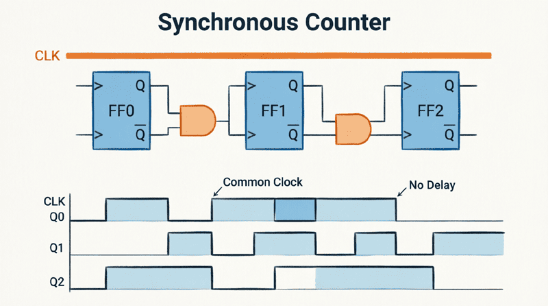
To overcome the speed and glitch limitations of asynchronous designs, Synchronous Bidirectional Counters are used in high-performance applications. In this architecture, the direction control logic dictates the Toggle (T) or J/K inputs of the flip-flops, rather than the clock inputs.
Circuit Architecture
In a synchronous design, the external clock is connected in parallel to all flip-flops. The AND-OR logic network calculates the toggle condition for each stage.
Toggle Logic Equations for a 3-Bit Synchronous Up/Down Counter:
- FF0 (LSB): Always toggles.
$J_0 = K_0 = 1$ - FF1: Toggles if counting UP and $Q_0=1$, OR if counting DOWN and $\overline{Q_0}=1$.
$J_1 = K_1 = (DIR \cdot Q_0) + (\overline{DIR} \cdot \overline{Q_0})$ - FF2: Toggles if counting UP and ($Q_0 \cdot Q_1 = 1$), OR if counting DOWN and ($\overline{Q_0} \cdot \overline{Q_1} = 1$).
$J_2 = K_2 = (DIR \cdot Q_0 \cdot Q_1) + (\overline{DIR} \cdot \overline{Q_0} \cdot \overline{Q_1})$
Using Multiplexers (MUX)
In modern digital design, especially within FPGAs and ASICs, Multiplexers are often preferred over discrete AND-OR gates for direction control. A 2-to-1 MUX can cleanly select between the UP logic path and the DOWN logic path based on the $DIR$ signal, reducing logic depth and improving timing performance.
Advantages of the Synchronous Approach
- High Speed: The clock is not routed through the logic gates. The gates only drive the J/K inputs, allowing the counter to operate at the maximum frequency of the flip-flops.
- Glitch-Free: Because all state changes occur on the same clock edge, there are no intermediate ripple states, ensuring clean and reliable decoding.
Common Bidirectional Counter Integrated Circuits (ICs)
While discrete flip-flop designs are excellent for learning, practical engineering relies on dedicated counter ICs. These chips integrate the flip-flops, direction logic, preset inputs, and reset functions into a single package.
1. 74LS193 / 74HC193 (4-Bit Binary Up/Down Counter)
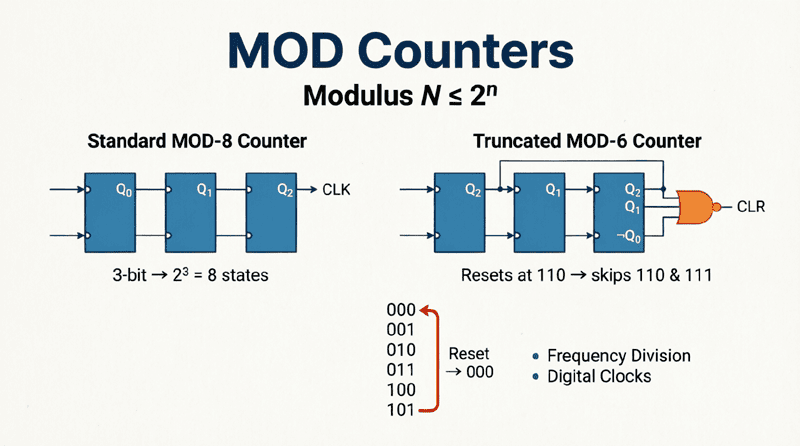
- Type: Synchronous, 4-bit binary (MOD-16).
- Direction Control: Features two separate active-LOW clock inputs: $CPU$ (Count Up) and $CPD$ (Count Down). To count up, pulses are applied to $CPU$ while $CPD$ is held HIGH, and vice versa.
- Features: Asynchronous parallel load, asynchronous master reset, and terminal count outputs for cascading.
2. 74LS192 / 74HC192 (4-Bit BCD Up/Down Counter)
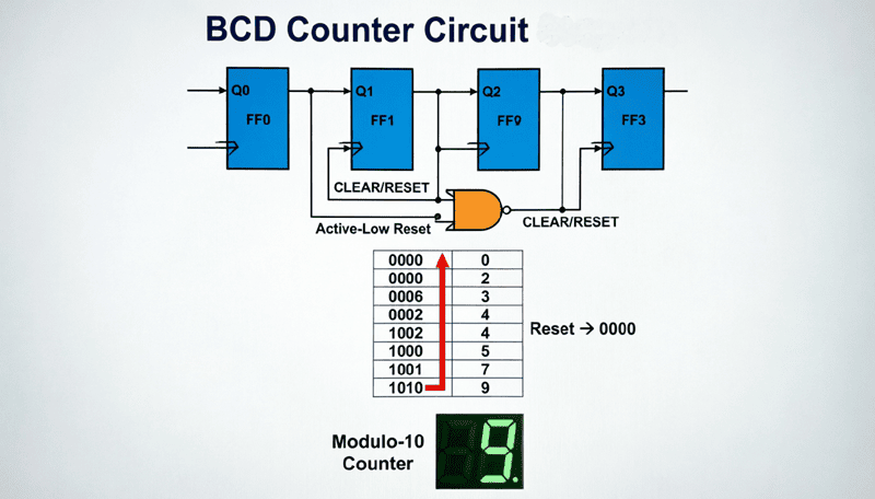
- Type: Synchronous, 4-bit BCD (MOD-10).
- Operation: Counts from 0000 to 1001 (0 to 9).
- Applications: Ideal for digital clocks, timers, and any application requiring decimal counting rather than binary.
3. 4029 (CMOS 4-Bit Up/Down Counter)
- Type: Synchronous, CMOS technology.
- Features: Can be configured as Binary (MOD-16) or BCD (MOD-10) via a mode pin. Features a dedicated $UP/DOWN$ control pin (active HIGH for UP, active LOW for DOWN).
- Advantage: Very low power consumption, making it ideal for battery-operated devices.
What is the difference between the 74LS193 and 74LS192?
The 74LS193 is a 4-bit binary counter that counts from 0 to 15 (MOD-16). The 74LS192 is a 4-bit BCD (Binary-Coded Decimal) counter that counts from 0 to 9 (MOD-10). Both are synchronous bidirectional counters with separate up and down clock inputs.
Practical Applications of Bidirectional Counters
The ability to count in both directions opens the door to numerous real-world applications where tracking reversible physical or logical processes is required.
1. Stepper Motor and Servo Motor Control
Stepper motors move in discrete steps. To control the position of a motor, a bidirectional counter is used to track the number of steps taken from a home position.
- Moving Forward: The controller sends pulses to the motor driver and increments the counter.
- Moving Backward: The controller reverses the phase sequence of the motor and decrements the counter.
- Position Tracking: The current value of the counter represents the exact physical position of the motor shaft.
2. Digital Clocks and Timers
When setting the time on a digital clock, you don’t wait for the clock to count up to the correct time. You use “Set” buttons that act as the direction control.
- Pressing “Hour +” sends pulses to the UP clock input of the hour counter.
- Pressing “Hour -” sends pulses to the DOWN clock input, allowing you to quickly rewind the time.
3. CNC Machines and 3D Printers
Computer Numerical Control (CNC) machines and 3D printers use bidirectional counters in their motion controllers. As the print head or cutting tool moves along the X, Y, and Z axes, bidirectional counters track the exact coordinates. If the machine needs to return to the origin (0,0,0), the counters simply decrement until they reach zero.
4. Frequency Synthesizers and Phase-Locked Loops (PLLs)
In radio frequency (RF) design, bidirectional counters are used in the feedback loop of a Phase-Locked Loop. The counter compares the phase of the reference frequency with the divided output frequency. If the output is too high, the control logic decrements the divider ratio; if it’s too low, it increments it, locking the frequency precisely.
5. Inventory and Event Tracking
In automated manufacturing, bidirectional counters track items on a conveyor belt. An entry sensor increments the counter when an item enters a zone, and an exit sensor decrements the counter when the item leaves. The counter’s value always represents the exact number of items currently inside the zone.
Step-by-Step Design Example: 2-Bit Synchronous Bidirectional Counter
Let’s walk through the complete logic design of a 2-bit synchronous bidirectional counter using D flip-flops.
Step 1: Define the States and Transitions
We need a 2-bit counter (Q1, Q0).
- If $DIR = 1$: 00 → 01 → 10 → 11 → 00
- If $DIR = 0$: 00 → 11 → 10 → 01 → 00
Step 2: Create the Excitation Table
For D flip-flops, the next state ($Q_{next}$) is simply the D input. We map the current state ($Q_1, Q_0$) and $DIR$ to the next state ($D_1, D_0$).
| DIR | Q1 | Q0 | Next Q1 (D1) | Next Q0 (D0) |
|---|---|---|---|---|
| 0 | 0 | 0 | 1 | 1 |
| 0 | 0 | 1 | 0 | 0 |
| 0 | 1 | 0 | 0 | 1 |
| 0 | 1 | 1 | 1 | 0 |
| 1 | 0 | 0 | 0 | 1 |
| 1 | 0 | 1 | 1 | 0 |
| 1 | 1 | 0 | 1 | 1 |
| 1 | 1 | 1 | 0 | 0 |
Step 3: Derive the Boolean Equations (Using K-Maps)
By simplifying the truth table using Karnaugh Maps, we get the following logic equations:
For D0 (LSB):
$D_0 = \overline{Q_0}$
(Notice that the LSB always toggles, regardless of the direction!)
For D1 (MSB):
$D_1 = (DIR \cdot Q_1 \cdot \overline{Q_0}) + (DIR \cdot \overline{Q_1} \cdot Q_0) + (\overline{DIR} \cdot Q_1 \cdot Q_0) + (\overline{DIR} \cdot \overline{Q_1} \cdot \overline{Q_0})$
This simplifies to:
$D_1 = Q_1 \oplus (DIR \oplus Q_0)$
(Where $\oplus$ represents the XOR operation).
Step 4: Implement the Circuit
- Connect the clock to both D flip-flops.
- Connect $\overline{Q_0}$ to $D_0$.
- Use two XOR gates to implement the $D_1$ equation:
- XOR Gate 1 inputs: $DIR$ and $Q_0$.
- XOR Gate 2 inputs: Output of XOR Gate 1 and $Q_1$.
- Output of XOR Gate 2 connects to $D_1$.
This elegant XOR implementation is highly efficient and commonly used in FPGA designs for bidirectional counters.
Bidirectional counters are a vital evolution of basic digital counters, providing the flexibility to track reversible processes in both physical and logical domains. By integrating direction control logic—typically through AND-OR gates, multiplexers, or XOR gates—these circuits can seamlessly switch between incrementing and decrementing sequences based on a single control signal.
Key takeaways from this guide include:
- Direction Control: The core mechanism relies on selecting between the normal ($Q$) and inverted ($\overline{Q}$) outputs of flip-flops using combinational logic controlled by a $DIR$ pin.
- Asynchronous vs. Synchronous: Asynchronous designs route the logic to the clock inputs (suffering from propagation delay), while synchronous designs route the logic to the J/K or D inputs (offering high speed and glitch-free operation).
- Dedicated ICs: Chips like the 74LS193 (Binary) and 74LS192 (BCD) provide robust, pre-engineered solutions for up/down counting, featuring parallel load and reset capabilities.
- Real-World Utility: From stepper motor positioning and CNC coordinate tracking to setting digital clocks and managing inventory zones, bidirectional counters are indispensable in modern electronics.
- Logic Optimization: Using XOR gates for synchronous D flip-flop designs provides a highly efficient, minimal-gate implementation for bidirectional counting.
Understanding how to design and implement bidirectional counters bridges the gap between theoretical sequential logic and practical, real-world digital system design. Whether you are building a simple timer or a complex motion control system, the up/down counter is a fundamental tool in your digital engineering arsenal.