AC-DC Converters
AC-DC Converters: The Complete Guide to Power Supply Design and Topologies
Introduction to AC-DC Conversion
AC-DC converters are the backbone of modern electronics, transforming the alternating current (AC) from wall outlets into the direct current (DC) required by virtually all electronic devices. From smartphone chargers to laptop power adapters, from industrial motor drives to renewable energy systems, AC-DC conversion is essential for powering our digital world.
The fundamental challenge of AC-DC conversion lies in efficiently transforming high-voltage AC (120V or 230V RMS) into stable, regulated low-voltage DC (typically 3.3V, 5V, 12V, or 24V) while maintaining safety, efficiency, and reliability. This process involves several stages: voltage transformation, rectification, filtering, and regulation.
Understanding AC-DC converters is crucial for:
- Designing power supplies for electronic devices
- Selecting appropriate converters for specific applications
- Troubleshooting power supply issues
- Optimizing efficiency and thermal performance
- Ensuring electromagnetic compatibility (EMC)
- Meeting safety standards and regulations
This comprehensive guide will explore the theory, circuits, and practical implementation of AC-DC converters, from basic rectifier circuits to advanced switch-mode power supplies (SMPS).
What is an AC-DC Converter?
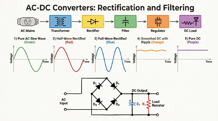
An AC-DC converter is an electronic circuit that converts alternating current (AC) from the mains supply into direct current (DC) suitable for electronic devices. It typically includes a transformer for voltage reduction, rectifier to convert AC to pulsating DC, filter capacitor to smooth the output, and regulator to provide stable voltage.
Types of AC-DC Converters
AC-DC converters can be broadly classified into two main categories: linear power supplies and switching power supplies (SMPS). Each has distinct characteristics, advantages, and applications.
Linear Power Supplies
Operating Principle:
Linear power supplies use a simple approach:
- Step down AC voltage using a transformer
- Rectify AC to DC using diodes
- Filter with capacitors
- Regulate using a linear regulator (series pass transistor)
Advantages:
- Simple design and construction
- Low output ripple and noise
- Fast transient response
- No electromagnetic interference (EMI)
- Low cost for low-power applications
Disadvantages:
- Low efficiency (30-60% typical)
- Large and heavy (due to transformer)
- Significant heat dissipation
- Limited to low-power applications (< 50W typically)
- Poor regulation with input voltage variations
Efficiency Calculation:
For a linear regulator:
$$\text{Efficiency} = \frac{V_{out}}{V_{in}} \times 100\%$$
Example: Converting 12V to 5V:
$$\text{Efficiency} = \frac{5V}{12V} \times 100\% = 41.7\%$$
The remaining 58.3% is dissipated as heat!
Applications:
- Audio equipment (low noise requirement)
- Laboratory power supplies
- Low-power analog circuits
- RF equipment
Switching Power Supplies (SMPS)
Operating Principle:
Switching power supplies use high-frequency switching to achieve efficient conversion:
- Rectify and filter AC input to high-voltage DC
- Chop DC into high-frequency AC (20 kHz to several MHz)
- Step down using high-frequency transformer
- Rectify and filter to DC output
- Feedback control regulates output voltage
Advantages:
- High efficiency (70-95% typical)
- Compact and lightweight
- Wide input voltage range
- Better regulation
- Can provide multiple outputs
- Suitable for high-power applications
Disadvantages:
- More complex design
- Higher output ripple and noise
- Generates EMI (requires filtering)
- Slower transient response
- Higher cost for low-power applications
Efficiency Calculation:
For an SMPS:
$$\text{Efficiency} = \frac{P_{out}}{P_{in}} \times 100\% = \frac{V_{out} \times I_{out}}{V_{in} \times I_{in}} \times 100\%$$
Typical efficiencies:
- Flyback converter: 70-85%
- Forward converter: 75-90%
- LLC resonant: 90-95%
Applications:
- Computer power supplies
- Phone/laptop chargers
- LED drivers
- Industrial equipment
- Telecommunications
What’s the difference between linear and switching power supplies?
Linear power supplies are simple, low-noise, but inefficient (30-60%) and bulky. Switching power supplies (SMPS) are complex but highly efficient (70-95%), compact, and lightweight. Linear is best for low-noise applications; SMPS is best for efficiency and size.
Rectifier Circuits: Converting AC to Pulsating DC
Rectification is the first critical step in AC-DC conversion, converting alternating current into unidirectional (pulsating) DC.
Half-Wave Rectifier
Circuit Configuration:
- Single diode in series with load
- Simplest rectifier topology
- Only conducts during positive half-cycle
Operation:
- Positive half-cycle: Diode forward-biased, conducts
- Negative half-cycle: Diode reverse-biased, blocks
Output Characteristics:
- Average DC voltage: $V_{DC} = \frac{V_m}{\pi} = 0.318 V_m$
- RMS voltage: $V_{RMS} = \frac{V_m}{2}$
- Ripple frequency: Equal to input frequency (50/60 Hz)
- Efficiency: 40.6% (theoretical maximum)
Disadvantages:
- Low efficiency
- High ripple content
- Poor transformer utilization
- Only uses half the AC cycle
Applications: Rarely used in modern power supplies; mainly for signal detection.
Full-Wave Center-Tapped Rectifier
Circuit Configuration:
- Center-tapped transformer
- Two diodes
- Each diode conducts on alternate half-cycles
Operation:
- Positive half-cycle: D1 conducts, D2 blocks
- Negative half-cycle: D2 conducts, D1 blocks
- Both cycles produce positive output
Output Characteristics:
- Average DC voltage: $V_{DC} = \frac{2V_m}{\pi} = 0.637 V_m$
- RMS voltage: $V_{RMS} = \frac{V_m}{\sqrt{2}}$
- Ripple frequency: 2× input frequency (100/120 Hz)
- Efficiency: 81.2% (theoretical maximum)
Advantages:
- Better efficiency than half-wave
- Lower ripple
- Better transformer utilization
Disadvantages:
- Requires center-tapped transformer (expensive)
- Each diode sees 2× peak inverse voltage (PIV)
- Only half the transformer secondary is used at a time
Full-Wave Bridge Rectifier
Circuit Configuration:
- Four diodes in bridge configuration
- Standard transformer (no center tap required)
- Most popular rectifier topology
Operation:
- Positive half-cycle: D1 and D3 conduct
- Negative half-cycle: D2 and D4 conduct
- Current flows through load in same direction
Output Characteristics:
- Average DC voltage: $V_{DC} = \frac{2V_m}{\pi} – 2V_d$ (accounting for 2 diode drops)
- RMS voltage: $V_{RMS} = \frac{V_m}{\sqrt{2}}$
- Ripple frequency: 2× input frequency (100/120 Hz)
- Efficiency: 81.2% (theoretical maximum)
Advantages:
- No center-tapped transformer needed
- Better transformer utilization
- Lower PIV per diode ($V_m$ instead of $2V_m$)
- Most cost-effective solution
Disadvantages:
- Two diode drops reduce output voltage
- Slightly more complex than center-tapped
Diode Selection:
- Peak Inverse Voltage (PIV): $PIV \geq V_m$ (with 2× safety margin)
- Average current: $I_{avg} \geq \frac{I_{load}}{2}$
- Surge current rating for capacitor charging
Example Calculation:
For 120V AC input (RMS):
- Peak voltage: $V_m = 120 \times \sqrt{2} = 170V$
- Required PIV: $170V \times 2 = 340V$ minimum
- Use diodes rated for 400V or 600V (standard: 1N4004, 1N4007)
What is the output voltage of a bridge rectifier?
For a bridge rectifier with AC input voltage Vrms, the average DC output is VDC = (2×Vpeak/π) – 2Vdiode. For 120V AC input: VDC ≈ (2×170/3.14) – 1.4V ≈ 107V DC (before filtering).
Filtering: Smoothing the Pulsating DC
After rectification, the output is pulsating DC with significant ripple. Filtering smooths this waveform to produce steady DC voltage.
Capacitor Input Filter
Circuit Configuration:
- Large electrolytic capacitor across output
- Most common filtering method
- Simple and effective
Operation:
- Capacitor charges to peak voltage during conduction
- Discharges through load during non-conduction
- Maintains voltage between peaks
Ripple Voltage Calculation:
$$V_{ripple} = \frac{I_{load}}{f \times C}$$
Where:
- $I_{load}$ = Load current (A)
- $f$ = Ripple frequency (Hz) = 2× line frequency for full-wave
- $C$ = Capacitance (F)
Example:
For 1A load, 120 Hz ripple (full-wave, 60 Hz input), 1000µF capacitor:
$$V_{ripple} = \frac{1A}{120 Hz \times 0.001F} = 8.33V$$
Capacitor Selection:
- Voltage rating: ≥ 1.5× peak voltage
- Capacitance: Based on acceptable ripple
- Ripple current rating: Must handle charging current
- Temperature rating: 85°C or 105°C preferred
Rule of Thumb:
For full-wave rectifier:
$$C (\mu F) \approx \frac{I_{load} (mA)}{2 \times V_{ripple} (V)}$$
For 1A load with 1V ripple:
$$C \approx \frac{1000}{2 \times 1} = 500 \mu F$$
Use 1000µF for margin.
LC Filter (Choke Input)
Circuit Configuration:
- Inductor in series with load
- Capacitor in parallel with load
- Better regulation than capacitor-only
Advantages:
- Lower peak currents
- Better voltage regulation
- Reduced stress on rectifier diodes
- Lower ripple
Disadvantages:
- Larger and heavier (inductor)
- More expensive
- Slower transient response
Applications: High-current power supplies, audio equipment
π (Pi) Filter
Circuit Configuration:
- Capacitor-Inductor-Capacitor (CLC)
- Combines advantages of both filters
Advantages:
- Excellent ripple reduction
- Good regulation
- Lower output impedance
Disadvantages:
- Higher cost
- Larger size
- Inrush current issues
Voltage Regulation: Maintaining Stable Output
Even with filtering, the output voltage varies with load and input changes. Regulation provides a stable, precise output voltage.
Linear Voltage Regulators
Types:
1. Fixed Regulators (78xx series):
- 7805: 5V output
- 7812: 12V output
- 7815: 15V output
- Simple 3-pin design (input, output, ground)
2. Adjustable Regulators (LM317):
- Output adjustable from 1.25V to 37V
- Requires two external resistors
- Better flexibility
Operation:
- Series pass transistor drops excess voltage
- Feedback maintains constant output
- Dissipates power as heat: $P_{diss} = (V_{in} – V_{out}) \times I_{load}$
Advantages:
- Simple design
- Low output ripple
- Fast transient response
- Low cost
- Built-in protection (overcurrent, thermal)
Disadvantages:
- Low efficiency
- Heat dissipation
- Requires heat sink for high current
- Input must be higher than output (dropout voltage)
Dropout Voltage:
Minimum voltage difference between input and output:
- Standard regulators: 2-3V
- LDO (Low Dropout): 0.1-0.5V
Example:
LM7805 with 12V input, 500mA load:
$$P_{diss} = (12V – 5V) \times 0.5A = 3.5W$$
Requires heat sink!
Switching Regulators
Topologies:
1. Buck Converter (Step-Down):
- Output voltage < Input voltage
- High efficiency (85-95%)
- Most common for DC-DC conversion
2. Boost Converter (Step-Up):
- Output voltage > Input voltage
- Used for battery-powered devices
3. Buck-Boost Converter:
- Output can be higher or lower than input
- Inverted output polarity
4. Flyback Converter:
- Isolated output (transformer)
- Multiple outputs possible
- Common in AC-DC adapters
Operation:
- High-frequency switching (20 kHz – 2 MHz)
- Energy storage in inductor/capacitor
- PWM control for regulation
- Feedback loop maintains output
Advantages:
- High efficiency (70-95%)
- Minimal heat dissipation
- Compact size
- Wide input range
- Can step up or down
Disadvantages:
- Complex design
- Output ripple and noise
- EMI generation
- Higher cost
- Slower transient response
IC Examples:
- LM2596: Buck converter, 3A, simple
- LM2577: Boost converter
- UC384x: PWM controller
- TOPSwitch: Integrated flyback
Practical Design Example: 12V DC Power Supply
Let’s design a complete AC-DC converter for a 12V, 2A output.
Specifications:
- Input: 120V AC, 60 Hz
- Output: 12V DC, 2A maximum
- Ripple: < 100mV peak-to-peak
- Regulation: ±5%
Design Steps:
Step 1: Transformer Selection
- Secondary voltage: 15V AC (RMS)
- Current rating: 2A minimum
- Power rating: 15V × 2A = 30VA
- Use 50VA transformer for margin
Step 2: Rectifier Design
- Bridge rectifier configuration
- Peak voltage: $V_m = 15 \times \sqrt{2} = 21.2V$
- DC output (no load): $V_{DC} = 21.2V – 1.4V = 19.8V$
- Diode rating: PIV ≥ 50V, Iavg ≥ 1A
- Use: 1N5401 (3A, 100V) or KBPC5010 (bridge, 5A)
Step 3: Filter Capacitor
- Allowable ripple: 100mV = 0.1V
- Load current: 2A
- Ripple frequency: 120 Hz (full-wave)
$$C = \frac{I_{load}}{f \times V_{ripple}} = \frac{2A}{120 Hz \times 0.1V} = 166,667 \mu F$$
This is impractically large! Let’s recalculate with realistic values:
For 2V ripple (more realistic):
$$C = \frac{2A}{120 Hz \times 2V} = 8,333 \mu F$$
Use: 10,000µF, 35V electrolytic capacitor
Step 4: Voltage Regulator
Option A: Linear Regulator (LM7812)
- Input voltage: ~18V (after ripple)
- Output: 12V
- Dropout: 2V minimum
- Power dissipation: $(18V – 12V) \times 2A = 12W$
- Requires large heat sink!
Option B: Switching Regulator (Buck converter)
- Use LM2596-12 or similar
- Efficiency: ~85%
- Power dissipation: Much lower
- Smaller heat sink or none
Step 5: Output Capacitor
- For linear regulator: 10µF tantalum + 0.1µF ceramic
- For switching regulator: 100-470µF low-ESR electrolytic
Complete Circuit:
120V AC → Transformer (15V AC) → Bridge Rectifier →
10,000µF Cap → LM2596 (Buck) → 12V DC @ 2A
Safety Considerations
Working with AC-DC converters involves high voltages. Always follow these safety guidelines:
Isolation Requirements
- Transformer provides galvanic isolation
- Maintain creepage and clearance distances
- Use insulated enclosures
- Fuse on primary side
Protection Circuits
- Input fuse: Protects against short circuits
- MOV (Metal Oxide Varistor): Surge protection
- Thermal fuse: Over-temperature protection
- Output overcurrent protection: Prevents damage
EMI/EMC Compliance
- Input EMI filter (common-mode choke + X/Y capacitors)
- Shielding for high-frequency switching supplies
- Proper grounding
- Meet FCC/CE regulations
AC-DC converters are fundamental building blocks of modern electronics, transforming mains AC power into regulated DC voltages. Understanding the trade-offs between linear and switching topologies, proper rectifier selection, filtering techniques, and regulation methods is essential for designing reliable power supplies.
Key takeaways from this guide:
- Rectification: Bridge rectifiers are the most practical choice for full-wave conversion
- Filtering: Capacitor input filters are simple and effective; size based on acceptable ripple
- Linear vs. Switching: Linear supplies are simple and low-noise but inefficient; SMPS are efficient and compact but complex
- Regulation: Choose linear regulators for low noise and simplicity; switching regulators for efficiency and high power
- Design: Always consider safety, thermal management, and component ratings with appropriate margins
- Efficiency: SMPS can achieve 85-95% efficiency; linear supplies typically 30-60%
Whether you’re designing a simple 5V charger or a complex multi-output industrial power supply, the principles outlined in this guide provide the foundation for creating safe, efficient, and reliable AC-DC converters.