Frequency Division
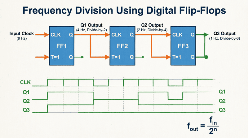
Frequency Division: Complete Guide to Digital Frequency Dividers
Introduction to Frequency Division
Frequency division is a fundamental technique for creating lower-frequency clock signals from higher-frequency sources. This process is essential for countless applications, from generating precise timing signals for microprocessors to creating audio oscillators and communication systems.
Frequency division is the process of taking a high-frequency clock signal and producing a lower-frequency output signal whose frequency is a precise fraction of the input frequency. For example, a divide-by-2 circuit takes a 10 MHz input and produces a 5 MHz output; a divide-by-10 circuit creates a 1 MHz output from the same 10 MHz input.
The need for frequency division arises in numerous scenarios:
- Clock Generation: Creating multiple clock frequencies from a single crystal oscillator
- Digital Timing: Generating precise timing signals for microcontrollers and digital systems
- Communication Systems: Creating baud rates from master clock sources
- Audio Applications: Generating musical tones and audio signals
- Measurement Instruments: Creating timebases for oscilloscopes and counters
This comprehensive guide will explore the theory, design, and practical implementation of frequency division circuits, from simple flip-flop-based dividers to complex counter circuits. We’ll examine the different types of frequency dividers, their circuit implementations, and their applications across various electronic systems.
What is Frequency Division?
Frequency division is the process of creating a lower-frequency signal from a higher-frequency clock source. It’s achieved using digital counters or flip-flops that divide the input clock frequency by a specific integer value (N), resulting in an output frequency of f_in/N. Frequency division is essential for clock generation, timing circuits, and signal processing.
Understanding Frequency Division
Basic Principle
The fundamental principle of frequency division is simple: count clock cycles and generate an output pulse after a specific number of cycles.
For example, to create a divide-by-2 circuit:
- Count 2 clock cycles
- Toggle the output after each count
- Result: Output frequency = Input frequency / 2
The general formula for frequency division is:
$f_{out} = \frac{f_{in}}{N}$
Where:
- $f_{out}$ = Output frequency
- $f_{in}$ = Input frequency
- $N$ = Division ratio (integer)
The Role of Digital Counters
Digital counters are the primary building blocks for frequency division. A counter is a sequential logic circuit that counts clock pulses and produces an output that represents the number of pulses counted.
How Counters Enable Frequency Division:
- A counter increments its value with each clock pulse
- When the counter reaches a specific value (the division ratio), it resets
- The reset action can be used to generate the output pulse
The output frequency is:
$f_{out} = \frac{f_{in}}{N}$
Where N is the counter’s modulus (the number of states it cycles through).
Flip-Flops as Basic Frequency Dividers
The simplest frequency divider is a single T flip-flop (toggle flip-flop) or a D flip-flop configured as a toggle:
Divide-by-2 Circuit:
- A single T flip-flop toggles its output with each clock pulse
- Output frequency = Input frequency / 2
- This is the most basic frequency division circuit
Divide-by-4 Circuit:
- Two T flip-flops cascaded
- First flip-flop: divide-by-2
- Second flip-flop: divide-by-2 (of the first output)
- Overall: divide-by-4
The principle extends to any integer division ratio using multiple flip-flops or a counter circuit.
Types of Frequency Dividers
1. Binary Counters
Binary counters divide the input frequency by powers of 2:
$f_{out} = \frac{f_{in}}{2^n}$
Where n is the number of flip-flops in the counter.
Example:
- 3-bit binary counter (8 states): divide-by-8
- 4-bit binary counter (16 states): divide-by-16
- 8-bit binary counter (256 states): divide-by-256
Binary counters are simple to implement and widely used for dividing clock frequencies by powers of 2.
2. Presettable Counters
Presettable counters allow division by any integer value, not just powers of 2:
$f_{out} = \frac{f_{in}}{N}$ (where N is any integer)
How it works:
- The counter is preset to a specific value
- It counts up (or down) to a terminal count
- On terminal count, it resets to the preset value
- The division ratio is N = Terminal count – Preset value + 1
Example:
- Preset to 10, terminal count = 15
- N = 15 – 10 + 1 = 6
- Division ratio = 6
3. Programmable Frequency Dividers
Programmable frequency dividers allow the division ratio to be changed dynamically:
- Division ratio controlled by digital inputs
- Can divide by different values at different times
- Used in frequency synthesizers and PLL circuits
4. Fractional-N Frequency Dividers
Fractional-N dividers create non-integer division ratios:
$f_{out} = \frac{f_{in}}{N + \frac{K}{M}}$
Where N, K, and M are integers.
Applications:
- Precise frequency synthesis
- Communication systems requiring precise frequencies
- Clock recovery circuits
Circuit Implementation of Frequency Dividers
1. T Flip-Flop Frequency Divider
The simplest frequency divider is a single T flip-flop:
T Flip-Flop as Divide-by-2

       __________
Clock --|          |----- Q (Output)
       |   T FF   |
Reset --|__________|----- Q̄
Operation:
- T (Toggle) input is permanently high
- Output toggles on each clock edge
- Output frequency = Clock frequency / 2
- Duty cycle = 50% (for symmetrical clock)
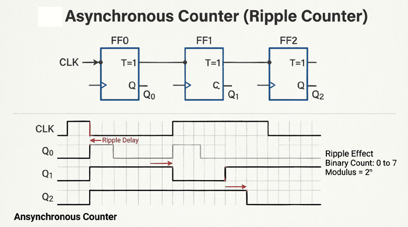
2. Ripple (Asynchronous) Counter
A ripple counter uses flip-flops connected in series:
4-bit Ripple Counter

Clock --| T FF |---| T FF |---| T FF |---| T FF |--- Output
        | Q0  |   | Q1  |   | Q2  |   | Q3  |
        |_____|   |_____|   |_____|   |_____|
Operation:
- Each flip-flop divides by 2
- Q0: divide-by-2
- Q1: divide-by-4
- Q2: divide-by-8
- Q3: divide-by-16
- Output: divide-by-16
Characteristics:
- Simple implementation
- Low component count
- Propagation delay accumulates through stages
- Output glitches possible
- Limited maximum clock frequency
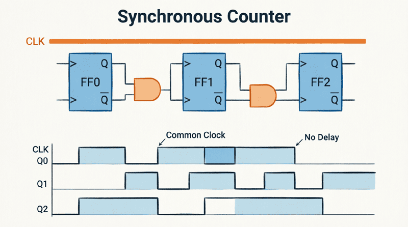
3. Synchronous Counter
Synchronous counters have all flip-flops clocked simultaneously:
4-bit Synchronous Counter

       ___________     ___________     ___________     ___________
Clock -|           |---|           |---|           |---|           |--- Output
       |   Synchronous |   Synchronous |   Synchronous |   Synchronous |
       |   Counter   |   Counter   |   Counter   |   Counter   |
       |___________|   |___________|   |___________|   |___________|
Operation:
- All flip-flops share the same clock
- Output changes simultaneously
- No propagation delay accumulation
- Higher maximum clock frequency
- More complex control logic
4. Presettable Counter with Divide-by-N
A presettable counter divides by any integer N:
Presettable Counter

       ___________
Clock -|           |
       | Presettable |
       |   Counter  |
       |___________|
           |
           | Output
Operation:
- Counter is preset to a specific value
- Counts to terminal count
- On terminal count, resets to preset value
- Division ratio N = Terminal count – Preset value + 1
Example:
- Preset = 10 (1010 in binary)
- Terminal count = 15 (1111)
- N = 15 – 10 + 1 = 6
- Output frequency = Input frequency / 6
Practical Applications of Frequency Division
1. Clock Generation for Microprocessors
Modern microprocessors require multiple clock frequencies:
Example:
- 100 MHz crystal oscillator
- Divide-by-2: 50 MHz (CPU clock)
- Divide-by-4: 25 MHz (bus clock)
- Divide-by-10: 10 MHz (peripheral clock)
Benefits:
- Single crystal for multiple frequencies
- Synchronization of different system components
- Power optimization (lower frequency for less critical components)
2. Communication Systems
Frequency division creates baud rates and carrier frequencies:
Example:
- 10 MHz clock
- Divide-by-100: 100 kHz (UART baud rate)
- Divide-by-1000: 10 kHz (modem clock)
Applications:
- Serial communication (UART)
- Modems and data transmission
- Radio frequency synthesis
3. Audio and Music Generation
Frequency division creates musical tones:
Example:
- 4 MHz clock
- Divide-by-4000: 1 kHz (A6 note)
- Divide-by-8000: 500 Hz (A5 note)
Applications:
- Simple tone generators
- Music synthesizers
- Audio test equipment
4. Digital Clocks and Timers
Frequency division creates precise time bases:
Example:
- 32.768 kHz crystal (standard watch crystal)
- Divide-by-32768: 1 Hz (1-second pulse)
- This 1 Hz pulse drives the seconds display
Applications:
- Digital clocks
- Timers and interval timers
- Real-time clocks (RTC)
5. Measurement Instruments
Frequency division creates timebases for oscilloscopes:
Example:
- 100 MHz clock
- Divide-by-100: 1 MHz (timebase)
- Divide-by-1000: 100 kHz (slower timebase)
Applications:
- Oscilloscopes
- Frequency counters
- Timing analyzers
Frequency Division Circuit Design
Design Process
- Determine Requirements:
- Input frequency
- Required output frequency
- Division ratio (N)
- Duty cycle requirements
- Timing constraints
- Select Circuit Type:
- Binary counter (if N is power of 2)
- Presettable counter (if N is any integer)
- Synchronous counter (for high-speed applications)
- Ripple counter (for simple, low-speed applications)
- Calculate Component Values:
- Number of flip-flops required
- Preset value (for presettable counters)
- Timing parameters
- Implement and Test:
- Build circuit
- Verify division ratio
- Check for glitches
- Measure duty cycle
Example: Divide-by-6 Circuit Design
Problem: Design a divide-by-6 frequency divider using a 74LS193 counter (4-bit presettable counter).
Solution:
Step 1: Determine Requirements
- Input: 6 MHz clock
- Output: 1 MHz clock
- Division ratio: N = 6
- 74LS193 counter (4-bit, presettable)
Step 2: Select Circuit Type
- 74LS193 is a 4-bit presettable counter
- Can be configured for any division ratio up to 16
Step 3: Calculate Component Values
- 74LS193 counts from preset value to terminal count (15 for 4-bit counter)
- N = Terminal count – Preset value + 1
- For N = 6:
- 6 = 15 – Preset + 1
- Preset = 15 – 6 + 1 = 10
- Preset value = 10 (1010 in binary)
Step 4: Circuit Implementation
- Connect counter output to:
- Preset inputs: A=0, B=1, C=0, D=1 (binary 1010)
- Clock input: 6 MHz clock
- Terminal count (RCO): Connect to preset (active low)
Step 5: Verification
- When counter reaches 15 (1111), it resets to 10 (1010)
- Counting sequence: 10, 11, 12, 13, 14, 15, 10…
- Number of states: 6
- Output frequency = 6 MHz / 6 = 1 MHz
Advanced Frequency Division Techniques
1. Multi-Stage Frequency Division
Multiple division stages create high division ratios:
Example:
- Stage 1: Divide-by-10 (10 MHz → 1 MHz)
- Stage 2: Divide-by-100 (1 MHz → 10 kHz)
- Overall: Divide-by-1000
Benefits:
- Achieves high division ratios with simple circuits
- Reduces timing constraints on individual stages
- More reliable than single-stage high division
2. Fractional-N Frequency Division
Fractional-N division creates non-integer division ratios:
$f_{out} = \frac{f_{in}}{N + \frac{K}{M}}$
Implementation:
- Uses a phase-locked loop (PLL)
- Combines integer division with phase accumulation
- Creates precise frequency synthesis
Applications:
- Frequency synthesizers
- Radio transmitters/receivers
- Clock recovery circuits
3. Programmable Frequency Dividers
Programmable frequency dividers change division ratio dynamically:
Implementation:
- Uses digital inputs to select division ratio
- Can be controlled by microprocessor
- Often implemented as part of a PLL
Applications:
- Software-defined radio
- Reconfigurable systems
- Test equipment
4. Dual-Modulus Prescalers
Dual-modulus prescalers combine two division ratios:
$f_{out} = \frac{f_{in}}{M \times N + K}$
Implementation:
- Uses a counter that switches between two division ratios
- Creates more precise frequency synthesis
Applications:
- High-precision frequency synthesis
- Communication systems
Frequency Division in Modern Systems
1. PLL-Based Frequency Synthesis
Phase-Locked Loop (PLL) circuits combine frequency division with feedback:
PLL BLOCK

       _________     _________     _________
Input -|  VCO  |-----|  ÷N   |-----|  Phase  |--- Output
       |_______|     |_______|     |  Detector |
                    |       |-----|_________|
                    |  ÷M   |     |         |
                    |_______|     |  Loop   |
                    |       |-----|  Filter |
                    |  ÷K   |     |_________|
Operation:
- VCO (Voltage-Controlled Oscillator) generates output
- ÷N divider creates feedback signal
- Phase detector compares input and feedback
- Loop filter smooths error signal
- Feedback adjusts VCO frequency
Benefits:
- Precise frequency control
- Low phase noise
- Fast locking
2. Digital Clock Management
Modern FPGAs and microcontrollers include sophisticated clock management:
Features:
- Multiple clock dividers
- Phase shifters
- Clock multiplexers
- Clock gating
- Dynamic frequency scaling
Applications:
- Power management (reducing clock frequency to save power)
- Performance optimization (increasing clock frequency for critical tasks)
- Clock domain crossing (synchronizing between clock domains)
3. Software-Defined Frequency Division
Software-defined approaches for frequency division:
Implementation:
- Using digital signal processing (DSP) techniques
- Implementing division in software
- Using direct digital synthesis (DDS)
Applications:
- Reconfigurable systems
- Test equipment
- Signal processing
Common Problems and Solutions
1. Clock Skew and Timing Errors
Problem:
- Asynchronous counters can have significant clock skew
- Output glitches can occur
- Timing errors affect system stability
Solutions:
- Use synchronous counters for high-speed applications
- Add output registers to stabilize outputs
- Use clock management circuits to reduce skew
2. Glitches in Output
Problem:
- Ripple counters can have output glitches
- When multiple bits change simultaneously, intermediate states can cause glitches
Solutions:
- Use synchronous counters
- Add output registers to capture stable values
- Use Gray code counting for applications requiring minimal glitches
3. Limited Maximum Frequency
Problem:
- Ripple counters have limited maximum clock frequency
- Propagation delay accumulates through stages
Solutions:
- Use synchronous counters
- Implement with faster logic families (e.g., CMOS instead of TTL)
- Use dedicated frequency divider ICs
Frequency division is a fundamental technique in digital electronics that enables the creation of precise lower-frequency signals from higher-frequency clock sources. By understanding the different types of frequency dividers and their circuit implementations, engineers can design systems with precise timing characteristics.
Key takeaways from this guide include:
- Fundamental Principle: Frequency division creates lower-frequency signals from higher-frequency sources using counters or flip-flops.
- Circuit Types:
- Binary counters divide by powers of 2
- Presettable counters divide by any integer
- Synchronous counters offer better timing performance
- Ripple counters are simpler but slower
- Design Process:
- Determine requirements (input/output frequency)
- Select circuit type based on division ratio
- Calculate component values
- Implement and test
- Advanced Techniques:
- Multi-stage division for high ratios
- Fractional-N division for precise frequencies
- PLL-based synthesis for high precision
- Programmable dividers for flexibility
- Applications:
- Clock generation for microprocessors
- Communication systems
- Audio and music generation
- Digital clocks and timers
- Measurement instruments
Understanding frequency division is crucial for anyone working with digital systems, from simple microcontroller projects to complex communication systems. The ability to create precise clock signals from a single source is fundamental to modern electronics design.
As you continue your journey in digital electronics, remember that frequency division is just one aspect of the broader clock management and timing techniques that form the backbone of reliable digital systems. Mastering these concepts will enable you to design systems with precise timing characteristics, optimize power usage, and create reliable digital circuits.