BCD Counter Circuit
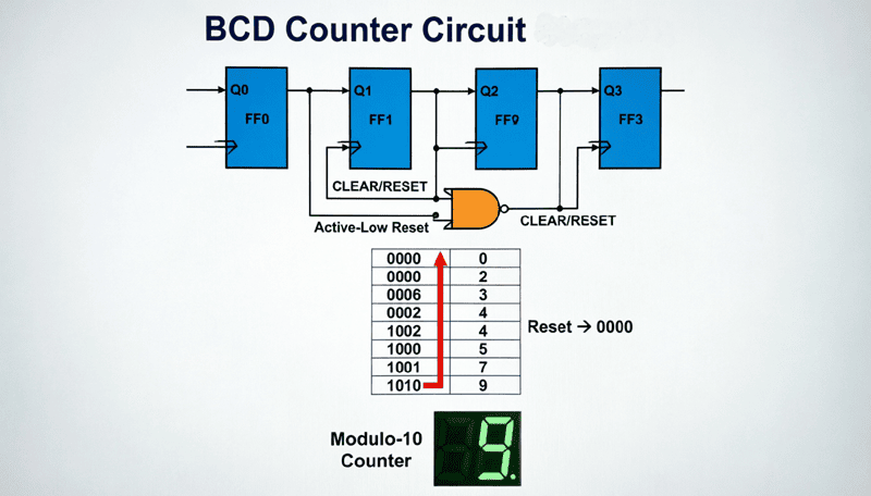
BCD Counter Circuit: Complete Guide to Decimal Counting Design
Introduction to BCD Counters
In the world of digital electronics, while binary counting is fundamental, human interaction with digital systems often requires decimal (base-10) representation. This is where the BCD (Binary-Coded Decimal) Counter, also known as a Decade Counter or MOD-10 Counter, becomes essential.
A BCD counter is a sequential logic circuit that counts from 0 to 9 (decimal) and then resets to 0, skipping the binary states 10 through 15. Unlike a standard 4-bit binary counter that counts from 0000 to 1111 (0 to 15 in decimal), a BCD counter only utilizes the first ten states (0000 to 1001), making it ideal for applications requiring decimal display or human-readable counting.
BCD counters are the backbone of numerous everyday electronic devices:
- Digital Clocks and Watches: Displaying hours, minutes, and seconds
- Calculators: Performing arithmetic operations
- Digital Multimeters: Showing measurement readings
- Frequency Counters: Displaying frequency values
- Timers and Stopwatches: Tracking elapsed time
- Industrial Counters: Counting products or events
This comprehensive guide will explore the architecture, design methodology, and practical implementation of BCD counter circuits. We will examine integrated circuits like the 74LS90 and 74LS192, discuss how to cascade multiple BCD counters for multi-digit displays, and explore their critical role in digital systems that interface with humans.
What is a BCD Counter?
A BCD (Binary-Coded Decimal) counter is a digital circuit that counts from 0 to 9 (0000 to 1001 in binary) and then resets to 0. It’s also called a decade counter or MOD-10 counter because it has 10 distinct states. Unlike binary counters that count to 15, BCD counters skip states 10-15, making them ideal for decimal displays.
Understanding BCD (Binary-Coded Decimal)
What is BCD?
Binary-Coded Decimal (BCD) is a encoding scheme where each decimal digit (0-9) is represented by a 4-bit binary number. Unlike pure binary representation, BCD maintains the decimal structure, making it easier to convert to and from human-readable decimal numbers.
BCD Encoding Table:
| Decimal | BCD (4-bit) | Binary (4-bit) |
|---|---|---|
| 0 | 0000 | 0000 |
| 1 | 0001 | 0001 |
| 2 | 0010 | 0010 |
| 3 | 0011 | 0011 |
| 4 | 0100 | 0100 |
| 5 | 0101 | 0101 |
| 6 | 0110 | 0110 |
| 7 | 0111 | 0111 |
| 8 | 1000 | 1000 |
| 9 | 1001 | 1001 |
| 10 | 0001 0000 | 1010 |
| 15 | 0001 0101 | 1111 |
Key Difference:
- Binary 10 = 1010 (one binary number)
- BCD 10 = 0001 0000 (two BCD digits: ‘1’ and ‘0’)
Why Use BCD Instead of Pure Binary?
Advantages of BCD:
- Easy Decimal Conversion: Direct mapping to decimal digits simplifies display driving
- Human-Readable: Easier for humans to understand and verify
- No Rounding Errors: Exact decimal representation (important for financial calculations)
- Simple Display Interface: Direct connection to 7-segment displays
Disadvantages:
- Inefficient: Uses more bits than pure binary (4 bits for 10 states vs. 4 bits for 16 states)
- Complex Arithmetic: Addition and subtraction require special algorithms
- Invalid States: States 1010-1111 are unused and must be handled
Why do we use BCD counters instead of binary counters?
BCD counters are used when decimal display is required because each BCD digit (0-9) maps directly to a 7-segment display. While binary is more efficient (4 bits can represent 0-15), BCD (0-9 only) eliminates the need for complex binary-to-decimal conversion, making it ideal for clocks, calculators, and measurement instruments.
Designing BCD Counters
Method 1: Using Reset Logic with Binary Counter
The simplest way to create a BCD counter is to modify a standard 4-bit binary counter (MOD-16) to reset when it reaches 10 (1010 in binary).
Design Approach:
- Use a 4-bit binary counter (4 flip-flops)
- Detect when the count reaches 1010 (decimal 10)
- Use the detection signal to asynchronously reset all flip-flops
- The counter resets to 0000, skipping states 10-15
Reset Detection Logic:
To detect state 10 (1010):
- Q3 = 1 (MSB)
- Q2 = 0
- Q1 = 1
- Q0 = 0 (LSB)
Simplified Detection:
Since we only need to detect 1010, we can use:
- Reset = Q3 · Q1 (AND gate with Q3 and Q1)
This works because 1010 is the first state where both Q3 and Q1 are HIGH.
Circuit Implementation:
- 4 JK or D flip-flops configured as binary counter
- 2-input AND gate with inputs Q3 and Q1
- AND gate output connected to CLEAR (reset) inputs of all flip-flops
- When count = 1010, reset activates immediately, returning to 0000
Timing Consideration:
The reset is asynchronous, meaning it happens immediately when the condition is met, not waiting for the next clock edge. This creates a very brief glitch at state 10 before resetting to 0.
Method 2: Synchronous BCD Counter
For applications requiring glitch-free operation, a synchronous BCD counter is preferred. In this design, the reset logic is incorporated into the flip-flop input equations, ensuring all state changes occur on the clock edge.
Design Process:
- Create a state transition table for states 0-9
- Use Karnaugh maps to derive flip-flop input equations
- Implement with synchronous flip-flops (all clocked together)
- Ensure states 10-15 transition to 0
Advantages:
- No glitches or race conditions
- Predictable timing
- Better for high-speed applications
Disadvantages:
- More complex logic design
- Requires more gates
Method 3: Using Dedicated BCD Counter ICs
The most practical approach for real-world applications is to use dedicated BCD counter integrated circuits. These ICs have the reset logic and decade counting built-in, requiring minimal external components.
Popular BCD Counter ICs:
- 74LS90 / 74HC90: Asynchronous decade counter
- 74LS192 / 74HC192: Synchronous up/down BCD counter
- 4029: CMOS presettable BCD counter
- 4518: Dual BCD counter (two counters in one IC)
The 74LS90 Decade Counter IC
The 74LS90 (and its CMOS equivalent 74HC90) is one of the most popular and versatile BCD counter ICs. It’s a 4-bit asynchronous decade counter that can be configured for various counting modes.
Pin Configuration
14-Pin DIP Package:
- Pin 14: VCC (+5V)
- Pin 7: GND
- Pin 2, 3: Reset inputs (R0(1), R0(2)) – Active HIGH
- Pin 6, 7: Set inputs (R9(1), R9(2)) – Active HIGH (set to 9)
- Pin 14: Clock A (CLK A) – Input for divide-by-2 section
- Pin 1: Clock B (CLK B) – Input for divide-by-5 section
- Pins 12, 9, 8, 11: Outputs QA, QB, QC, QD (QA is LSB, QD is MSB)
Internal Architecture
The 74LS90 contains two independent counters:
- Divide-by-2 Counter: One flip-flop (clocked by CLK A, output QA)
- Divide-by-5 Counter: Three flip-flops (clocked by CLK B, outputs QB, QC, QD)
By connecting QA to CLK B, you create a complete divide-by-10 (BCD) counter.
Configurations
BCD (8421) Configuration:
- Connect QA (Pin 12) to CLK B (Pin 1)
- Apply clock to CLK A (Pin 14)
- Outputs: QA, QB, QC, QD (QD is MSB)
- Count sequence: 0000, 0001, 0010, …, 1001, 0000
Bi-Quinary Configuration:
- Connect QD (Pin 11) to CLK A (Pin 14)
- Apply clock to CLK B (Pin 1)
- Outputs: QB, QC, QD, QA
- Different output sequence but still MOD-10
Reset to Zero:
- Apply HIGH to both R0(1) and R0(2)
- Counter immediately resets to 0000
- R9(1) and R9(2) must be LOW
Set to Nine:
- Apply HIGH to both R9(1) and R9(2)
- Counter immediately sets to 1001 (9)
- R0(1) and R0(2) must be LOW
Example: Basic BCD Counter Circuit
Components:
- 74LS90 IC
- Push-button switch (for clock input)
- 4 LEDs (for output display)
- 4 current-limiting resistors (330Ω)
- 10kΩ pull-down resistor
- 9V battery with 5V regulator (or 5V supply)
Connections:
- VCC (Pin 14) to +5V, GND (Pin 7) to ground
- R0(1), R0(2), R9(1), R9(2) all to GND (disable reset/set)
- QA (Pin 12) to CLK B (Pin 1) – creates BCD configuration
- Clock signal to CLK A (Pin 14)
- QA, QB, QC, QD to LEDs through 330Ω resistors
Operation:
Each press of the button advances the counter by one. The LEDs display the BCD value from 0000 to 1001 (0 to 9), then reset to 0000.
How do you configure a 74LS90 as a BCD counter?
Connect QA (Pin 12) to CLK B (Pin 1) to cascade the divide-by-2 and divide-by-5 sections. Apply the clock signal to CLK A (Pin 14). Keep all reset pins (R0 and R9) LOW for normal counting. The outputs QA, QB, QC, QD will count from 0000 to 1001 (0-9) in BCD.
Cascading BCD Counters for Multi-Digit Displays
Single BCD counters count from 0 to 9. For applications requiring multi-digit counting (like a digital clock showing 00 to 99), you need to cascade multiple BCD counters.
Cascading Principle
When the first counter (units digit) completes a full cycle (0-9) and resets to 0, it should trigger the second counter (tens digit) to increment by one. This is achieved by using the carry output or the MSB transition of the first counter to clock the second counter.
Using 74LS90 for Cascading
Method 1: Using QD as Clock
- QD (MSB) of the first counter goes HIGH when count reaches 8
- QD goes LOW when count resets from 9 to 0
- This falling edge can clock the next counter
- Connect QD of Counter 1 to CLK A of Counter 2
Method 2: Using Ripple Clock (Better)
- The 74LS90 has a natural divide-by-10 output
- Use QA (which toggles every 5 input clocks in BCD mode) or derive a carry signal
- Better: Use the reset transition to generate a carry pulse
Practical Cascading Circuit:
For two 74LS90 counters (00 to 99):
Counter 1 (Units):
- Clock input: External clock signal
- QA to CLK B (BCD configuration)
- QD output to Counter 2 clock input
Counter 2 (Tens):
- Clock input: QD from Counter 1 (or derived carry)
- QA to CLK B (BCD configuration)
- Outputs: QB, QC, QD, QA (tens digit)
Using 74LS192 for Cascading
The 74LS192 is a synchronous up/down BCD counter with dedicated carry and borrow outputs, making cascading much cleaner.
Carry Output (Pin 12):
- Goes LOW when counting UP from 9 to 0
- Use this to clock the UP input of the next counter
Borrow Output (Pin 13):
- Goes LOW when counting DOWN from 0 to 9
- Use this to clock the DOWN input of the next counter
Cascading Connection:
- Carry of Counter 1 → UP clock of Counter 2
- Borrow of Counter 1 → DOWN clock of Counter 2
- All LOAD and CLEAR pins can be tied together for synchronous operation
Example: 3-Digit BCD Counter (000-999)
Components:
- 3 × 74LS90 ICs
- 3 × 74LS47 (BCD to 7-segment decoder/drivers)
- 3 × 7-segment common-anode displays
- Current-limiting resistors (for displays)
- Clock source (555 timer or crystal oscillator)
Connections:
- Counter 1 (Units):
- Clock: External clock
- QA to CLK B
- QD to Counter 2 CLK A
- Counter 2 (Tens):
- Clock: QD from Counter 1
- QA to CLK B
- QD to Counter 3 CLK A
- Counter 3 (Hundreds):
- Clock: QD from Counter 2
- QA to CLK B
- Outputs: QA, QB, QC, QD
- Display Interface:
- Each counter’s outputs (QA-QD) connect to a 74LS47 decoder
- 74LS47 outputs connect to 7-segment display
- Common-anode displays with current-limiting resistors
Operation:
The counter counts from 000 to 999, with each digit displayed on its own 7-segment display. When the units digit rolls from 9 to 0, it triggers the tens digit to increment, and so on.
BCD to 7-Segment Display Interface
BCD counters are most useful when their output is displayed in human-readable decimal form. This requires a BCD to 7-segment decoder/driver IC.
7-Segment Display Basics
A 7-segment display consists of 7 LEDs (segments) labeled a, b, c, d, e, f, g arranged in a figure-8 pattern. By illuminating specific segments, you can display digits 0-9.
Segment Patterns:
- 0: a, b, c, d, e, f (not g)
- 1: b, c
- 2: a, b, d, e, g
- 3: a, b, c, d, g
- 4: b, c, f, g
- 5: a, c, d, f, g
- 6: a, c, d, e, f, g
- 7: a, b, c
- 8: a, b, c, d, e, f, g (all)
- 9: a, b, c, d, f, g
Display Types:
- Common Anode: All LED anodes connected together to VCC. Segments turn ON when driven LOW.
- Common Cathode: All LED cathodes connected together to GND. Segments turn ON when driven HIGH.
74LS47 BCD to 7-Segment Decoder
The 74LS47 is a popular BCD to 7-segment decoder/driver designed for common-anode displays.
Pin Configuration:
- Pins 7, 1, 2, 6: BCD inputs (A, B, C, D where A is LSB)
- Pins 13, 12, 11, 10, 9, 15, 14: Segment outputs (a, b, c, d, e, f, g) – Active LOW
- Pin 3-5: Lamp test, blanking input, ripple blanking (for special functions)
- Pin 16: VCC (+5V)
- Pin 8: GND
Operation:
- Apply BCD code (0000-1001) to inputs A, B, C, D
- The 74LS47 decodes the BCD and activates the appropriate segments
- Outputs are active LOW (sink current) for common-anode displays
- Current-limiting resistors (330Ω) required for each segment
Example Connection:
74LS90 (BCD Counter)     74LS47 (Decoder)     7-Segment Display
QA (LSB)        ----->   A (Pin 7)            Segment a -----> Resistor -----> Display
QB            ----->   B (Pin 1)            Segment b -----> Resistor -----> Display
QC            ----->   C (Pin 2)            Segment c -----> Resistor -----> Display
QD (MSB)      ----->   D (Pin 6)            Segment d -----> Resistor -----> Display
                                               ... (segments e, f, g)
Common Anode of Display -----> +5V
Alternative: 74LS48 Decoder
For common-cathode displays, use the 74LS48, which has active-HIGH outputs that source current to the segments.
Practical Applications of BCD Counters
1. Digital Clocks and Timers
BCD counters are the heart of digital timekeeping circuits. A typical digital clock uses:
- Seconds: Two BCD counters (00-59)
- Minutes: Two BCD counters (00-59)
- Hours: Two BCD counters (00-23 or 01-12)
Special Considerations:
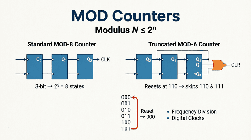
- MOD-6 Counters: For the tens digit of seconds/minutes (0-5), use a MOD-6 counter instead of MOD-10
- MOD-12 or MOD-24: For hours, custom reset logic is needed
2. Frequency Counters
Frequency counters measure the frequency of an input signal by counting pulses over a known time period (e.g., 1 second).
Design:
- Gate the input signal for exactly 1 second
- Count pulses using cascaded BCD counters
- Display the count (which equals frequency in Hz)
- Use multiple digits for higher frequencies (e.g., 6 digits for MHz range)
3. Digital Multimeters
Digital multimeters use BCD counters in their analog-to-digital conversion process, particularly in dual-slope integrating ADCs. The counter counts clock pulses during the integration period, and the final count represents the measured voltage.
4. Production Line Counters
In manufacturing, BCD counters track:
- Number of products produced
- Number of items packaged
- Machine cycle counts
- Quality control statistics
Features:
- Up/down counting for inventory management
- Preset values for batch counting
- Reset functionality for new production runs
5. Parking Lot Counters
BCD counters track the number of cars in a parking lot:
- Increment when a car enters (sensor at entrance)
- Decrement when a car exits (sensor at exit)
- Display remaining spaces
- Full indicator when count reaches maximum
Advanced BCD Counter Designs
Presettable BCD Counters
Some applications require starting the count from a specific value rather than zero. Presettable BCD counters like the 74LS192 allow you to load a specific BCD value into the counter.
74LS192 Features:
- Parallel load inputs (D0-D3)
- LOAD pin (active LOW) to load data
- UP and DOWN clock inputs
- Carry and borrow outputs for cascading
- Synchronous operation
Loading Procedure:
- Apply desired BCD value to D0-D3 inputs
- Pulse the LOAD pin LOW
- Counter loads the value on the next clock edge
- Resume normal counting
Synchronous vs. Asynchronous BCD Counters
Asynchronous (Ripple) Counters (74LS90):
- Advantages: Simple, low cost, minimal external components
- Disadvantages: Propagation delay, glitches, limited speed
- Best for: Low-frequency applications, simple displays
Synchronous Counters (74LS192, 74HC192):
- Advantages: No glitches, high speed, predictable timing
- Disadvantages: More complex, higher cost
- Best for: High-speed counting, precision applications, cascaded systems
Troubleshooting BCD Counter Circuits
Common Problems and Solutions
Problem 1: Counter Skips States
- Cause: Loose connections, noisy clock signal
- Solution: Check all connections, add decoupling capacitors (0.1µF) near IC power pins
Problem 2: Counter Doesn’t Reset at 9
- Cause: Faulty reset logic, incorrect wiring
- Solution: Verify AND gate connections for reset detection (Q3·Q1)
Problem 3: Display Shows Garbage
- Cause: Invalid BCD states (1010-1111), decoder mismatch
- Solution: Ensure counter resets properly at 10, verify 74LS47/74LS48 matches display type
Problem 4: Cascaded Counters Don’t Advance
- Cause: Incorrect carry connection, timing issues
- Solution: Verify QD or carry output connects to next counter’s clock, check for proper edge triggering
Problem 5: Counter Counts Backwards
- Cause: Clock signal noise, switch bounce
- Solution: Add debouncing circuit for mechanical switches, use Schmitt trigger for clock input
BCD counters are essential components in digital systems that require decimal counting and display. By limiting the count sequence to 0-9 (0000-1001), they provide a direct interface between binary digital logic and human-readable decimal numbers.
Key takeaways from this guide include:
- BCD Encoding: Each decimal digit (0-9) is represented by a 4-bit binary code (0000-1001), skipping states 1010-1111.
- Design Methods: BCD counters can be created using reset logic with binary counters, synchronous design with custom flip-flop inputs, or dedicated ICs like the 74LS90 and 74LS192.
- 74LS90 Operation: This versatile IC contains separate divide-by-2 and divide-by-5 sections that can be cascaded (QA to CLK B) to create a complete BCD counter.
- Cascading: Multiple BCD counters can be cascaded to create multi-digit counters (00-99, 000-999) by connecting the MSB or carry output of one counter to the clock input of the next.
- Display Interface: BCD counters work seamlessly with BCD-to-7-segment decoders (74LS47/74LS48) to drive 7-segment displays for human-readable output.
- Applications: From digital clocks and frequency counters to production line counters and parking lot systems, BCD counters are ubiquitous in real-world digital systems.
- Synchronous vs. Asynchronous: Choose asynchronous counters (74LS90) for simple, low-cost applications, and synchronous counters (74LS192) for high-speed, glitch-free operation.
Understanding BCD counters bridges the gap between pure binary digital logic and the decimal system humans use every day. Whether you’re building a simple digital clock or a complex measurement instrument, BCD counters provide the essential counting functionality that makes digital systems accessible and useful.
As you continue your journey in digital electronics, remember that BCD counters are just one example of how we adapt binary systems to meet human needs. The principles learned here—custom modulus counting, cascading, and display interfacing—apply to countless other digital design challenges.