The Inductor
The Complete Guide to How Inductors Work in Circuits
Introduction to the Inductor
In the vast world of electronic components, the inductor stands as one of the three fundamental passive elements, alongside the resistor and the capacitor. While a resistor opposes the flow of current and a capacitor opposes changes in voltage, an inductor uniquely opposes changes in current.
Visually, an inductor is typically just a coil of wire, but its electrical behavior is governed by the profound laws of electromagnetism. When current flows through this coil, it generates a magnetic field. If that current tries to change, the magnetic field changes with it, inducing a voltage that fights the change. This property, known as inductance, makes inductors indispensable in modern electronics, from filtering noise in power supplies to tuning radio frequencies and stepping voltages up or down in transformers.
Whether you are designing a switching power supply, building an RF oscillator, or simply trying to understand how your smartphone manages power, understanding the inductor is crucial. This comprehensive guide will explore the physics, construction, energy storage capabilities, and practical applications of the inductor, providing you with a solid foundation in electromagnetic circuit theory.
What is an Inductor?
An inductor is a passive electronic component that stores energy in a magnetic field when electric current flows through it. It consists of a coil of wire, often wound around a magnetic core. Its primary function is to oppose any change in the current flowing through it, a property known as inductance, measured in Henrys (H).
How an Inductor Works: The Physics of Electromagnetism
To truly understand how an inductor works, we must look at the relationship between electricity and magnetism. The operation of an inductor is based on two fundamental principles of physics: Electromagnetism and Electromagnetic Induction.
Electromagnetism
When an electric current flows through a straight wire, it generates a weak, circular magnetic field around the wire. If you wind that wire into a coil (a solenoid), the magnetic fields of each individual loop combine and concentrate through the center of the coil, creating a much stronger, unified magnetic field. The strength of this magnetic field is directly proportional to the amount of current flowing through the coil and the number of turns in the wire.
Faraday’s Law and Lenz’s Law
The magic of the inductor happens when the current changes.
Faraday’s Law of Induction states that a changing magnetic field within a coil of wire induces an electromotive force (EMF), or voltage, across the coil.
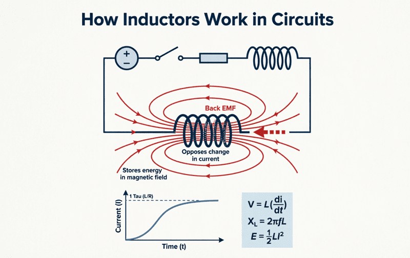
Lenz’s Law dictates the direction of this induced voltage. It states that the induced voltage will always act in a direction that opposes the change in current that created it. This opposing voltage is commonly referred to as Back EMF.
Imagine trying to push a heavy shopping cart. When you first push, it resists your forward motion (inertia). When you try to stop it, it resists your stopping force, wanting to keep rolling. An inductor acts as “electrical inertia.”
- If the current tries to increase, the inductor induces a voltage that pushes back, slowing the rise.
- If the current tries to decrease, the inductor induces a voltage that pushes forward, trying to keep the current flowing.
Why does an inductor oppose changes in current?
An inductor opposes changes in current due to Lenz’s Law. When current changes, the resulting change in the magnetic field induces a “back EMF” voltage across the coil. This induced voltage always acts in a direction that opposes the change in the original current flow.
Construction of an Inductor
The physical construction of an inductor directly determines its electrical characteristics. While the basic design is simple, the materials used can vastly alter its performance.
The Windings
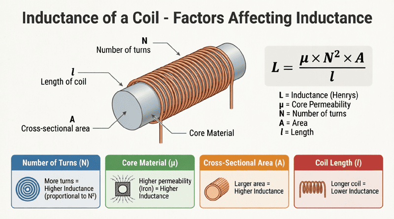
The core of any inductor is the winding, typically made of insulated copper or aluminum wire. The number of turns ($N$) in the coil is a primary factor in determining its inductance. More turns mean a stronger magnetic field for a given current, resulting in higher inductance. The wire must be insulated (often with a thin enamel coating) to prevent short circuits between adjacent loops.
The Core Material
The material placed inside the coil is called the core. The core’s magnetic permeability ($\mu$) dictates how easily it can support the formation of a magnetic field.
- Air Core: If the coil is wound around a non-magnetic form (like plastic or ceramic) or just hollow, it has an air core. Air has a very low permeability. Air-core inductors have low inductance but are excellent for high-frequency applications because they don’t suffer from core losses (heat generated by changing magnetic fields).
- Iron Core: Using laminated iron or steel dramatically increases the permeability, allowing for much higher inductance in a smaller physical size. These are typically used in low-frequency applications, like power supplies and audio chokes.
- Ferrite Core: Ferrite is a ceramic compound containing iron oxide. It has high permeability but is electrically insulating, which prevents eddy currents (circulating currents inside the core that cause heat). Ferrite cores are the standard for high-frequency inductors in modern electronics, such as switch-mode power supplies and RF circuits.
Energy Storage in an Inductor
Unlike a resistor, which dissipates electrical energy as heat, an ideal inductor stores energy. It does this in the form of a magnetic field.
When current begins to flow through an inductor, energy is drawn from the circuit to build up the magnetic field. Once the current reaches a steady state (in a DC circuit), the magnetic field is fully established, and the inductor draws no more energy. If the circuit is opened or the current decreases, the magnetic field collapses, and the stored energy is returned to the circuit.
The amount of energy ($W$) stored in an inductor’s magnetic field is calculated using the following formula:
$W = \frac{1}{2} L I^2$
Where:
- $W$ = Energy stored in Joules (J)
- $L$ = Inductance in Henrys (H)
- $I$ = Current flowing through the inductor in Amperes (A)
Notice that the energy stored is proportional to the square of the current. This means doubling the current quadruples the stored energy. This property makes inductors highly effective in applications where bursts of high energy are required, such as camera flashes, ignition coils in cars, and pulsed laser systems.
How does an inductor store energy?
An inductor stores energy in its magnetic field. The amount of energy stored (in Joules) is calculated by the formula W = ½LI², where L is the inductance in Henrys and I is the current in Amperes. When the current decreases, the magnetic field collapses and returns this stored energy to the circuit.
Inductor Behavior in DC vs. AC Circuits
The behavior of an inductor changes drastically depending on whether it is placed in a Direct Current (DC) or Alternating Current (AC) circuit.
In a DC Circuit
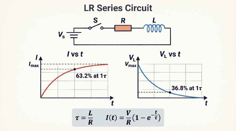
When a DC voltage is first applied to an inductor, the current tries to jump from zero to its maximum value instantly. The inductor fiercely opposes this sudden change, causing the current to rise gradually in an exponential curve.
However, once the current reaches a steady, constant value, the magnetic field stops changing. Because there is no change in the magnetic field, there is no induced back EMF. At this point, the inductor acts essentially as a short circuit (or more accurately, just a piece of wire with a very small amount of DC resistance).
In an AC Circuit
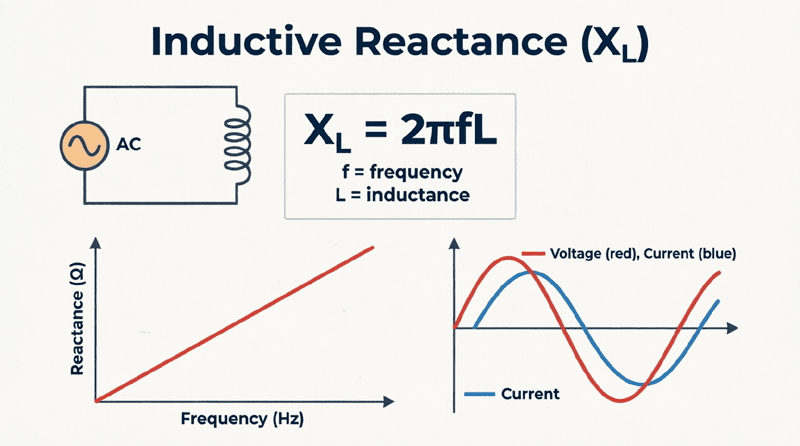
In an AC circuit, the current is constantly changing direction and magnitude (typically 50 or 60 times a second). Because the current is always changing, the inductor is always generating a back EMF to oppose it.
This continuous opposition to the alternating current is called inductive reactance ($X_L$). Unlike DC resistance, inductive reactance increases as the frequency of the AC signal increases. Therefore, in an AC circuit, an inductor acts as a frequency-dependent resistor, blocking high frequencies while allowing low frequencies to pass more easily.
Types of Inductors
Inductors are manufactured in various physical styles to suit different frequency ranges and power levels.
1. Air-Core Inductors
These use no magnetic core material. They have very low inductance values (typically in the microhenry, µH, range) but offer excellent high-frequency performance because they have zero core losses. They are widely used in RF (radio frequency) tuning circuits and high-frequency filters.
2. Iron-Core Inductors
These use laminated iron cores to achieve high inductance values (in the Henry, H, range). They are bulky and heavy but can handle high currents. They are primarily used in low-frequency applications, such as audio filtering and mains power chokes.
3. Ferrite-Core Inductors
Ferrite cores offer a middle ground. They provide high inductance in a compact size and can operate at much higher frequencies than iron cores without excessive heating. They are the most common type found on circuit boards, used in DC-DC converters, EMI filters, and telecommunications.
4. Toroidal Inductors
Instead of a straight bobbin, the wire is wound around a donut-shaped (toroidal) core. The closed-loop shape of the core contains the magnetic field entirely within the component, preventing it from interfering with nearby sensitive circuits. They are highly efficient and widely used in audio equipment and power supplies.
5. Variable Inductors
Similar to variable capacitors, these inductors have a movable core (usually made of ferrite) that can be screwed in or out of the coil. Moving the core changes the magnetic permeability, thereby tuning the inductance. They are used in older radio receivers for tuning specific frequencies.
Practical Applications of Inductors
The unique ability of inductors to store energy and block high-frequency AC makes them vital in countless electronic applications.
1. Chokes and EMI Filters
A “choke” is an inductor designed specifically to block high-frequency AC noise while allowing DC or low-frequency signals to pass. They are placed on power cables and circuit board inputs to prevent Electromagnetic Interference (EMI) from entering or leaving a device, ensuring regulatory compliance and clean power.
2. Switch-Mode Power Supplies (SMPS)
Modern power supplies (like your laptop charger) use inductors as temporary energy storage buckets. A high-frequency switch rapidly turns the current on and off. The inductor stores energy when the switch is on and releases it to the load when the switch is off, allowing for highly efficient voltage conversion (stepping voltage up or down) with minimal heat loss.
3. Transformers
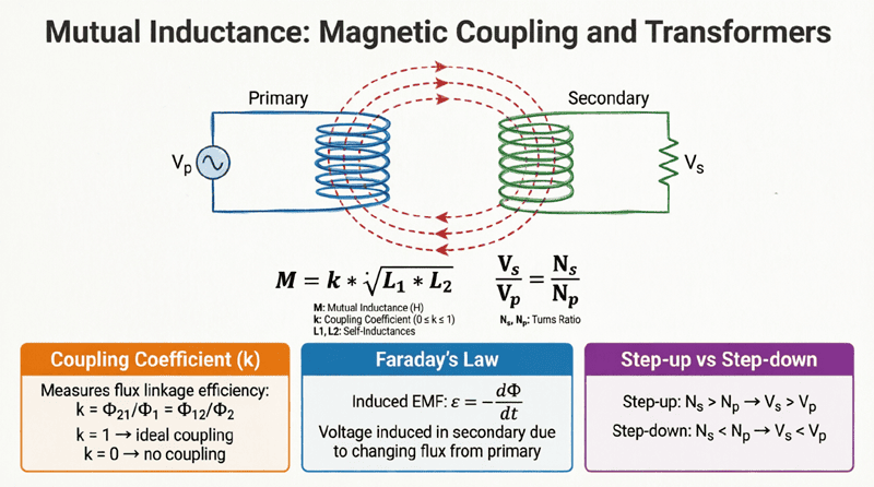
A transformer is essentially two or more inductors wound around a shared magnetic core. By exploiting mutual inductance, a changing current in the primary coil induces a voltage in the secondary coil. This is the foundational technology for stepping up voltages for long-distance power transmission and stepping them down for safe household use.
4. Tuned Circuits and Oscillators
When an inductor is paired with a capacitor, they form an LC “tank circuit.” This circuit resonates at a specific frequency, making it the core component of radio tuners, oscillators, and frequency filters. By adjusting the inductance or capacitance, you can select exactly which radio frequency to receive.
5. Electric Motors and Relays
The coils inside electric motors, solenoids, and relays are essentially large inductors. When current flows through them, they generate powerful magnetic fields that create physical motion (turning a motor shaft or pulling a mechanical switch).
The inductor is a fundamental passive component that brings the power of electromagnetism into electrical circuits. By storing energy in a magnetic field and opposing changes in current, it provides capabilities that resistors and capacitors simply cannot match.
Key takeaways from this guide include:
- Fundamental Behavior: An inductor opposes changes in current by generating a back EMF, governed by Faraday’s and Lenz’s laws.
- Energy Storage: It stores energy in a magnetic field, calculated by $W = \frac{1}{2}LI^2$.
- DC vs. AC: In DC, it acts as a short circuit once the current stabilizes. In AC, it presents inductive reactance, opposing the current flow.
- Core Materials: The choice of core (air, iron, ferrite) dictates the inductor’s inductance value, size, and frequency capabilities.
- Applications: From filtering noise and converting power in SMPS to tuning radios and driving motors, inductors are indispensable in modern electronics.
Understanding the inductor is the first step toward mastering AC circuit theory, power electronics, and RF design. As we delve deeper into the mathematics of inductance, reactance, and circuit analysis in the following articles, this foundational knowledge of how the physical component behaves will serve as your guiding light.