Multivibrators
Multivibrators: Complete Guide to Astable, Monostable, and Bistable Circuits
Introduction to Multivibrators
In the fascinating world of digital and analog electronics, multivibrators stand as one of the most fundamental and versatile circuit configurations. A multivibrator is an electronic circuit that switches between two or more states, generating square waves, rectangular pulses, or serving as a memory element.
The name “multivibrator” comes from the fact that the output waveform is rich in harmonics—it contains multiple frequencies (vibrations) of the fundamental frequency. These circuits are the backbone of timing applications, clock generation, pulse shaping, and digital memory systems.
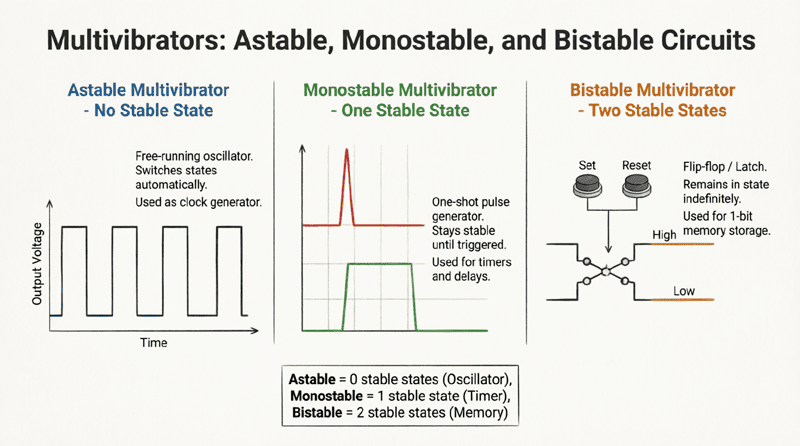
Multivibrators are classified into three main types based on their stability and operation:
- Astable Multivibrator: Has no stable state; continuously oscillates between HIGH and LOW.
- Monostable Multivibrator: Has one stable state; produces a single pulse when triggered.
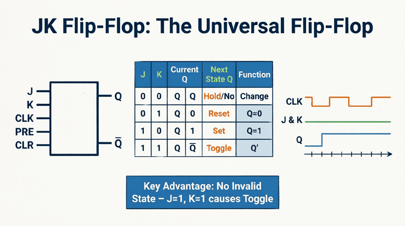
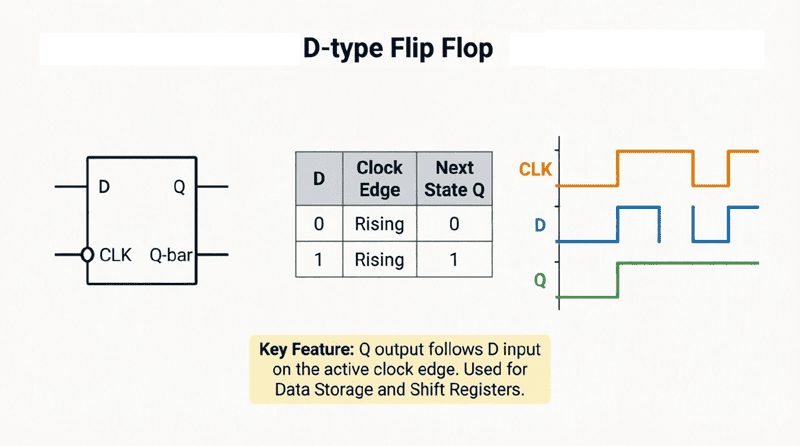
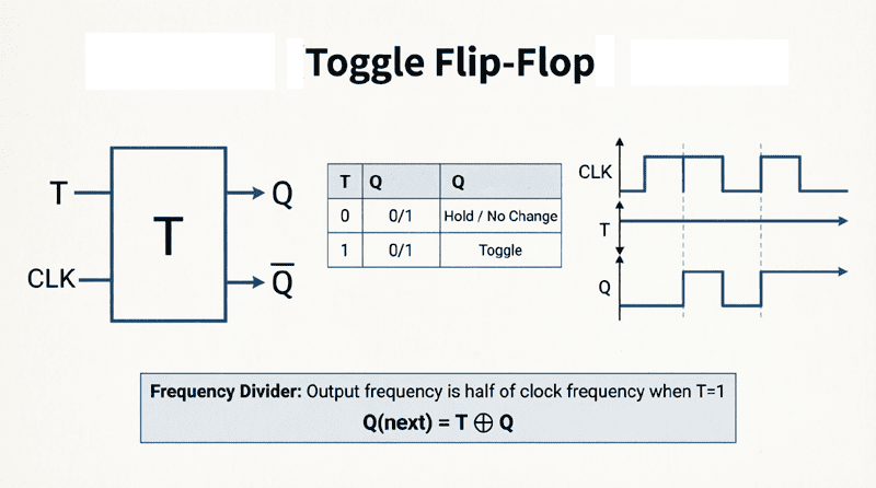
- Bistable Multivibrator: Has two stable states; acts as a memory element (flip-flop).
Understanding multivibrators is essential for designing oscillators, timers, pulse generators, and digital logic circuits. This comprehensive guide will explore each type in detail, including circuit diagrams, timing calculations, and practical applications using the famous 555 timer IC.
What is a Multivibrator?
A multivibrator is an electronic circuit that generates non-sinusoidal waveforms (square or rectangular waves) by switching between two voltage levels. It is classified into three types: astable (free-running oscillator), monostable (one-shot pulse generator), and bistable (flip-flop with two stable states).
The Three Types of Multivibrators
1. Astable Multivibrator (Free-Running)
The astable multivibrator has no stable state. It continuously oscillates between HIGH and LOW states without requiring any external trigger. This makes it a free-running oscillator.
Key Characteristics:
- Continuously generates square waves
- No external trigger required
- Used as clock generators, LED flashers, and tone generators
- The output frequency is determined by RC time constants
Applications:
- Digital clock circuits
- LED blinkers
- Tone generators for alarms
- Pulse width modulation (PWM)
- Function generators
2. Monostable Multivibrator (One-Shot)
The monostable multivibrator has one stable state (usually LOW) and one quasi-stable state (HIGH). When triggered by an external pulse, it switches to the quasi-stable state for a predetermined time period, then automatically returns to its stable state.
Key Characteristics:
- Requires an external trigger to activate
- Produces a single output pulse of fixed duration
- Returns to stable state automatically
- Pulse width is determined by RC time constant
Applications:
- Debouncing switches
- Pulse stretching
- Time delay circuits
- Missing pulse detectors
- Touch sensors
3. Bistable Multivibrator (Flip-Flop)
The bistable multivibrator has two stable states. It remains in one state indefinitely until an external trigger forces it to switch to the other state. This is essentially a flip-flop or latch.
Key Characteristics:
- Two stable states (0 and 1)
- Requires external triggers to change state
- Acts as a 1-bit memory element
- No automatic switching (no oscillation)
Applications:
- Digital memory storage
- Counters and registers
- Data latches
- Control logic circuits
What are the three types of multivibrators?
The three types are: 1) Astable – has no stable state and continuously oscillates (free-running); 2) Monostable – has one stable state and produces a single pulse when triggered (one-shot); 3) Bistable – has two stable states and acts as a memory element (flip-flop).
Astable Multivibrator: The Free-Running Oscillator
Circuit Operation
The classic astable multivibrator can be built using two transistors, two capacitors, and four resistors. However, the most popular implementation uses the 555 timer IC.
In a transistor-based astable multivibrator:
- Two transistors are cross-coupled through capacitors
- When one transistor is ON (saturated), the other is OFF (cut-off)
- The capacitors charge and discharge through resistors
- This causes the transistors to switch states alternately
- The result is a continuous square wave output
Frequency and Duty Cycle Calculations
For a 555 timer-based astable multivibrator:
Frequency Formula:
$$f = \frac{1.44}{(R_1 + 2R_2) \times C}$$
Where:
- $f$ = Output frequency in Hz
- $R_1, R_2$ = Timing resistors in ohms
- $C$ = Timing capacitor in farads
Time Period:
$$T = T_{HIGH} + T_{LOW}$$
$$T_{HIGH} = 0.693 \times (R_1 + R_2) \times C$$
$$T_{LOW} = 0.693 \times R_2 \times C$$
Duty Cycle:
$$Duty\ Cycle = \frac{T_{HIGH}}{T_{HIGH} + T_{LOW}} \times 100\%$$
$$Duty\ Cycle = \frac{R_1 + R_2}{R_1 + 2R_2} \times 100\%$$
Important Note: In a standard 555 astable configuration, the duty cycle is always greater than 50% because $T_{HIGH}$ is always longer than $T_{LOW}$. To achieve a 50% duty cycle (perfect square wave), you need to add a diode across $R_2$ or use a different circuit configuration.
Practical Example: LED Flasher
Problem: Design an astable multivibrator using a 555 timer to flash an LED at 1 Hz (once per second) with approximately 50% duty cycle.
Solution:
- Target frequency: $f = 1\ Hz$
- Time period: $T = 1/f = 1\ second$
- Choose $C = 10\mu F$
- Using the frequency formula:
$$1 = \frac{1.44}{(R_1 + 2R_2) \times 10 \times 10^{-6}}$$
$$R_1 + 2R_2 = \frac{1.44}{10 \times 10^{-6}} = 144,000\Omega = 144\ k\Omega$$
For 50% duty cycle, we need $R_1 << R_2$. Let’s choose:
- $R_1 = 1\ k\Omega$ (small)
- $R_2 = 71.5\ k\Omega$ (use 68 kΩ standard value)
This gives us approximately 1 Hz with near 50% duty cycle.
How do you calculate the frequency of an astable multivibrator?
For a 555 timer astable circuit: $f = 1.44 / ((R_1 + 2R_2) \times C)$. The HIGH time is $0.693 \times (R_1 + R_2) \times C$, and the LOW time is $0.693 \times R_2 \times C$. The duty cycle depends on the ratio of these resistors.
Monostable Multivibrator: The One-Shot Pulse Generator
Circuit Operation
The monostable multivibrator (also called a one-shot) has one stable state and one quasi-stable (temporary) state. In its stable state, the output is LOW. When a trigger pulse is applied, the output switches HIGH for a predetermined time period, then automatically returns to LOW.
Key Components:
- Trigger input (usually active LOW)
- Timing resistor (R) and capacitor (C)
- Output pulse width determined by RC time constant
Pulse Width Calculation
For a 555 timer-based monostable multivibrator:
Output Pulse Width:
$$T = 1.1 \times R \times C$$
Where:
- $T$ = Pulse width in seconds
- $R$ = Timing resistor in ohms
- $C$ = Timing capacitor in farads
Important Notes:
- The trigger pulse must be shorter than the output pulse width
- The circuit ignores additional triggers during the timing period (it’s “busy”)
- A reset pin can be used to abort the timing period early
Practical Example: Switch Debouncer
Problem: Design a monostable multivibrator to debounce a mechanical switch. The output should remain HIGH for 20ms after the switch is pressed.
Solution:
- Required pulse width: $T = 20\ ms = 0.02\ seconds$
- Choose $C = 1\mu F = 1 \times 10^{-6}\ F$
- Using the formula: $T = 1.1 \times R \times C$
$$0.02 = 1.1 \times R \times 1 \times 10^{-6}$$
$$R = \frac{0.02}{1.1 \times 10^{-6}} = 18,181\Omega$$
Use a standard 18 kΩ resistor.
This circuit will ignore any switch bounce (rapid on-off transitions) that occurs within the 20ms window, providing a clean, single output pulse.
Applications of Monostable Multivibrators
1. Switch Debouncing:
Mechanical switches bounce when pressed, creating multiple rapid transitions. A monostable circuit filters these out, providing a single clean pulse.
2. Pulse Stretching:
Converts a very short input pulse into a longer, more easily detectable output pulse.
3. Time Delay:
Creates a fixed delay between an input event and an output action.
4. Missing Pulse Detector:
If trigger pulses arrive regularly, the output stays HIGH. If a pulse is missed, the output goes LOW, indicating a fault.
5. Touch Sensors:
A brief touch triggers a timed output, useful for lamps, alarms, or interactive displays.
What is a monostable multivibrator used for?
A monostable multivibrator (one-shot) is used to generate a single output pulse of fixed duration when triggered. Common applications include switch debouncing, pulse stretching, time delay circuits, missing pulse detection, and touch sensors. The pulse width is calculated as $T = 1.1 \times R \times C$.
Bistable Multivibrator: The Digital Memory Element
Circuit Operation
The bistable multivibrator is fundamentally different from astable and monostable types. It has two stable states and will remain in either state indefinitely until an external trigger forces it to switch. This is the basic principle behind flip-flops and latches.
Key Characteristics:
- No timing capacitors (no automatic switching)
- Requires two separate triggers (SET and RESET)
- Acts as a 1-bit memory storage element
- Output remains stable until changed
SR Flip-Flop Implementation
The simplest bistable multivibrator is the SR (Set-Reset) flip-flop, which can be built using:
- Two cross-coupled NAND gates, or
- Two cross-coupled NOR gates
Operation:
- SET input HIGH: Output Q goes HIGH and stays HIGH
- RESET input HIGH: Output Q goes LOW and stays LOW
- Both inputs LOW: Output holds its previous state (memory)
- Both inputs HIGH: Invalid state (avoid this condition)
Applications of Bistable Multivibrators
1. Data Storage:
Each bistable circuit stores one bit of information (0 or 1). Millions of these form computer memory (RAM).
2. Counters:
Cascading bistable circuits creates binary counters that count clock pulses.
3. Shift Registers:
Bistable elements connected in series can shift data from one stage to the next.
4. Control Logic:
Used in state machines to remember the current state of a system.
5. Latches:
Temporarily hold data during processing or transmission.
The 555 Timer IC: The Ultimate Multivibrator
No discussion of multivibrators would be complete without mentioning the 555 timer IC. Introduced in 1971, the 555 is one of the most popular and versatile integrated circuits ever made. It can be configured as any of the three types of multivibrators.
555 Timer Pin Configuration
The standard 555 timer has 8 pins:
- Ground (GND): 0V reference
- Trigger (TRIG): Starts timing (active LOW)
- Output (OUT): Output signal
- Reset (RESET): Resets the timer (active LOW)
- Control Voltage (CTRL): Modifies threshold voltage
- Threshold (THRES): Ends timing (active HIGH)
- Discharge (DISCH): Discharges timing capacitor
- VCC: Power supply (+4.5V to +16V)
Advantages of the 555 Timer
- Simple to use: Requires few external components
- Versatile: Can be astable, monostable, or bistable
- Wide voltage range: Works from 4.5V to 16V
- High current output: Can source/sink up to 200mA
- Low cost: Extremely affordable
- Reliable: Time-tested design
Modern Alternatives
While the 555 timer is still widely used, modern alternatives include:
- CMOS 555 (7555): Lower power consumption
- Dual timers (556): Two 555s in one package
- Microcontrollers: Programmable timing with greater flexibility
- Specialized timer ICs: For specific applications
What is the 555 timer IC?
The 555 timer is a versatile integrated circuit that can be configured as an astable (oscillator), monostable (one-shot), or bistable (flip-flop) multivibrator. It requires few external components, works from 4.5V to 16V, and can source/sink up to 200mA, making it ideal for timing, pulse generation, and oscillator applications.
Practical Design Considerations
Component Selection
Resistors:
- Use 1% tolerance resistors for accurate timing
- Avoid values below 1kΩ (excessive current)
- Avoid values above 10MΩ (leakage currents affect timing)
Capacitors:
- Use low-leakage capacitors (ceramic, film, or tantalum)
- Avoid electrolytic capacitors for precise timing (high leakage)
- Temperature coefficient affects stability
Power Supply:
- Decouple the supply with a 0.1μF capacitor near the IC
- Ensure stable voltage for consistent timing
Troubleshooting Tips
Problem: No oscillation (astable)
- Check power supply connections
- Verify resistor and capacitor values
- Ensure discharge pin is connected correctly
Problem: Inaccurate frequency
- Check component tolerances
- Verify capacitor leakage
- Check for stray capacitance on PCB
Problem: Unstable output
- Add decoupling capacitors
- Check for noise on trigger/threshold pins
- Verify ground connections
Multivibrators are the fundamental building blocks of timing and memory in electronic circuits. Whether you need a continuous clock signal (astable), a single timed pulse (monostable), or a memory element (bistable), there’s a multivibrator configuration to meet your needs.
Key takeaways from this guide include:
- Astable Multivibrator:
- No stable state; continuously oscillates
- Used for clock generation and LED flashers
- Frequency: $f = 1.44 / ((R_1 + 2R_2) \times C)$
- Monostable Multivibrator:
- One stable state; produces single pulse when triggered
- Used for debouncing, timing, and pulse stretching
- Pulse width: $T = 1.1 \times R \times C$
- Bistable Multivibrator:
- Two stable states; acts as memory (flip-flop)
- Used for data storage and control logic
- Requires SET and RESET inputs
- The 555 Timer:
- Versatile IC that implements all three types
- Simple, reliable, and inexpensive
- Industry standard for timing applications
Mastering multivibrators opens the door to designing oscillators, timers, counters, and digital memory systems. Whether you’re building a simple LED flasher or a complex microcontroller-based system, the principles of multivibrators remain essential to modern electronics.