Quartz Crystal Oscillators
Quartz Crystal Oscillators: Complete Guide to Precision Timing Circuits
Introduction to Quartz Crystal Oscillators
In the realm of electronic timing and frequency generation, the Quartz Crystal Oscillator is the undisputed king of stability and precision. While LC oscillator and RC oscillator are excellent for general-purpose signal generation, their frequency drifts with temperature, component aging, and power supply variations. When an application demands exact, unwavering frequency accuracy—such as in microcontrollers, digital watches, GPS systems, and telecommunications—quartz crystals are the only viable choice.
The secret to the crystal’s supremacy lies in its extraordinarily high Quality Factor (Q), which can range from 10,000 to over 1,000,000. Compare this to a typical LC tank circuit with a Q of 100 to 300, and it becomes clear why crystals provide such narrow bandwidth and exceptional frequency stability (often within ±10 to ±100 parts per million, or ppm).
Understanding quartz crystal oscillators is essential for modern electronics design. Whether you are designing a printed circuit board (PCB) for a microcontroller, building a radio transceiver, or developing precision test equipment, knowing how to properly select, bias, and layout a crystal oscillator circuit is a fundamental engineering skill.
This comprehensive guide will explore the physics of the piezoelectric effect, the crystal’s electrical equivalent circuit, the difference between series and parallel resonance, and practical design guidelines for common crystal oscillator topologies.
What is a Quartz Crystal Oscillator?
A quartz crystal oscillator is an electronic circuit that uses the mechanical resonance of a vibrating quartz crystal to generate a highly stable and precise electrical signal. Due to the piezoelectric effect, the crystal acts as a high-Q resonant circuit, providing frequency stability far superior to LC or RC oscillators, typically within ±10 to 100 ppm.
The Physics of Quartz Crystals
The Piezoelectric Effect
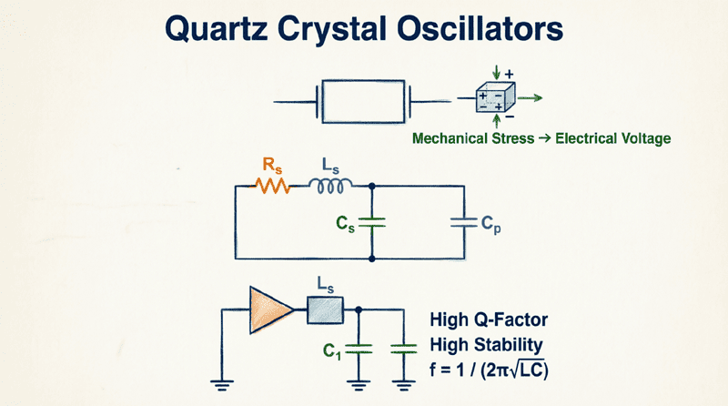
The operation of a quartz crystal oscillator is based on the piezoelectric effect, discovered by Pierre and Jacques Curie in 1880. This phenomenon occurs in certain asymmetric crystalline materials, including quartz (silicon dioxide, SiO₂).
The piezoelectric effect is bidirectional:
- Direct Piezoelectric Effect: When mechanical stress (pressure or bending) is applied to the crystal, it generates an electrical voltage across its surfaces.
- Reverse Piezoelectric Effect: When an electrical voltage is applied across the crystal, it physically deforms or changes shape.
In an oscillator circuit, these two effects work together to create a self-sustaining electromechanical feedback loop. An applied AC voltage causes the crystal to vibrate mechanically. This mechanical vibration, in turn, generates an AC voltage that reinforces the original electrical signal. When the frequency of the applied voltage matches the crystal’s natural mechanical resonant frequency, the vibration amplitude peaks, and the circuit oscillates.
The Crystal Equivalent Circuit
To analyze a crystal in an electronic circuit, we model it using an electrical equivalent circuit. This model accurately represents both the mechanical and electrical properties of the crystal.
The standard equivalent circuit consists of two parallel branches:
1. The Motional Arm (Series Branch):
This represents the mechanical vibration of the crystal.
- $L_m$ (Motional Inductance): Represents the mass of the vibrating crystal. (Typically very large, from millihenries to hundreds of henries).
- $C_m$ (Motional Capacitance): Represents the elasticity or compliance of the crystal. (Typically very small, from femtofarads to picofarads).
- $R_m$ (Motional Resistance or ESR): Represents the mechanical friction and electrical losses. (Typically a few ohms to a few hundred ohms).
2. The Shunt Arm (Parallel Branch):
- $C_0$ (Shunt or Static Capacitance): Represents the capacitance of the electrodes, holder, and wiring across the crystal. (Typically 2 pF to 7 pF).
Because $L_m$ is very large and $C_m$ is very small, the ratio $L_m / C_m$ is enormous. This is what gives the quartz crystal its phenomenally high Q factor:
$Q = \frac{1}{R_m} \sqrt{\frac{L_m}{C_m}}$
What is the equivalent circuit of a quartz crystal?
A quartz crystal is modeled as a series RLC circuit ($R_m$, $L_m$, $C_m$) representing its mechanical vibration, placed in parallel with a static shunt capacitance ($C_0$) representing the physical electrodes and holder. This unique combination yields an extremely high Quality Factor (Q).
Series vs. Parallel Resonance
Because of its unique equivalent circuit, a quartz crystal actually has two resonant frequencies. Understanding the difference between them is critical for proper circuit design.
1. Series Resonant Frequency ($f_s$)
At the series resonant frequency, the reactance of the motional inductance ($L_m$) exactly cancels the reactance of the motional capacitance ($C_m$). The series branch becomes purely resistive (equal to $R_m$), and the crystal’s impedance is at its minimum.
$f_s = \frac{1}{2\pi\sqrt{L_m C_m}}$
At $f_s$, the crystal acts like a very low-value resistor, allowing maximum current to flow. Oscillators designed to operate at $f_s$ are called series-mode crystal oscillators.
2. Parallel (Anti-Resonant) Frequency ($f_p$)
At a slightly higher frequency, the series branch becomes inductive. This inductive reactance resonates with the parallel shunt capacitance ($C_0$). At this point, the crystal’s impedance reaches its maximum, and it acts like a parallel LC tank circuit.
$f_p = f_s \sqrt{1 + \frac{C_m}{C_0}}$
Since $C_m$ is much smaller than $C_0$ (often by a factor of 1000 or more), $f_p$ is only slightly higher than $f_s$ (typically by 0.1% to 0.5%). This narrow region between $f_s$ and $f_p$ is where the crystal behaves inductively, which is the region used for parallel-mode crystal oscillators.
Which Mode to Use?
- Series Mode: Used when the crystal is placed in the feedback path of an amplifier with a gain of 1. The crystal acts as a highly selective series resistor. No external load capacitors are required.
- Parallel Mode: Used when the crystal is placed in the feedback path of an inverting amplifier (like a Pierce oscillator). The crystal acts as an inductor, and external load capacitors ($C_L$) are required to “pull” the frequency to the exact specified value. Most microcontroller crystals are specified for parallel mode.
Common Crystal Oscillator Topologies
1. The Pierce Oscillator
The Pierce oscillator is the most widely used crystal oscillator configuration, especially in digital electronics and microcontrollers. It is essentially a Colpitts oscillator where the inductor has been replaced by a quartz crystal.
Configuration:
- Uses a single inverting amplifier (a CMOS logic gate, a dedicated oscillator inverter, or a transistor).
- The crystal is connected between the input and output of the inverter.
- Two external capacitors ($C_1$ and $C_2$) are connected from each side of the crystal to ground.
- A large feedback resistor ($R_f$, typically 1 MΩ to 10 MΩ) is placed across the inverter to bias it into its linear region.
How it Works:
The inverter provides 180° of phase shift. The crystal, operating in its inductive region (between $f_s$ and $f_p$), combined with $C_1$ and $C_2$, provides the additional 180° of phase shift required for oscillation. $C_1$ and $C_2$ form a capacitive voltage divider that sets the feedback level and the load capacitance.
2. The Colpitts Crystal Oscillator
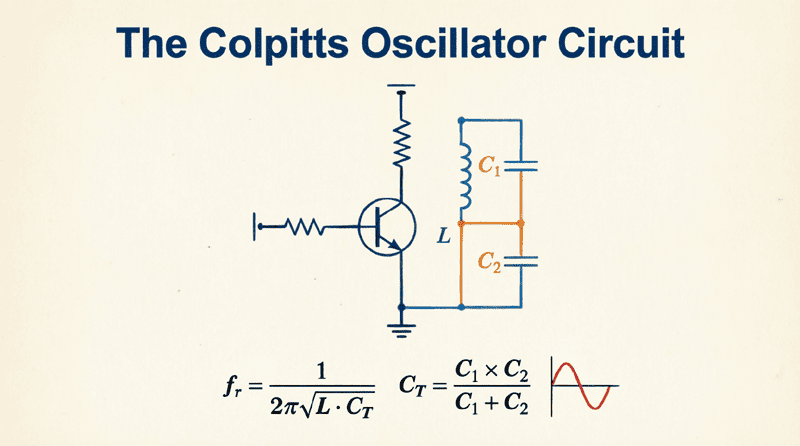
Similar to the standard LC Colpitts oscillator, this topology uses a transistor (BJT or FET) with a capacitive voltage divider. The crystal replaces the inductor in the tank circuit. It is highly stable and often used in RF applications where a transistor provides better high-frequency performance than a CMOS gate.
3. The Miller Crystal Oscillator
A variation of the Colpitts, the Miller oscillator uses a common-cathode (or common-source/common-emitter) configuration where the crystal is connected between the gate/base and ground, and the feedback is taken from the drain/collector. It is less common today but was historically used in vacuum tube and early transistor radios.
Practical Design Example: Microcontroller Pierce Oscillator
Let’s design a Pierce oscillator circuit for a standard microcontroller requiring a 16.000 MHz clock.
Step 1: Select the Crystal
Choose a parallel-mode quartz crystal.
- Frequency: 16.000 MHz
- Load Capacitance ($C_L$): 18 pF (a very common standard value)
- Equivalent Series Resistance (ESR or $R_m$): < 50 Ω
- Package: 3.2mm x 2.5mm SMD
Step 2: Calculate External Load Capacitors ($C_1$ and $C_2$)
The crystal manufacturer specifies the frequency based on a specific load capacitance ($C_L$). The circuit must provide this exact capacitance. The formula for the total load capacitance seen by the crystal is:
$C_L = \frac{C_1 \times C_2}{C_1 + C_2} + C_{stray}$
Where:
- $C_1, C_2$ = External capacitors
- $C_{stray}$ = Stray capacitance from PCB traces and microcontroller pins (typically estimated at 3 pF to 5 pF).
Assuming we use equal capacitors ($C_1 = C_2 = C$) for simplicity:
$C_L = \frac{C}{2} + C_{stray}$
Rearranging to solve for $C$:
$C = 2 \times (C_L – C_{stray})$
Given $C_L = 18 \text{ pF}$ and estimating $C_{stray} = 4 \text{ pF}$:
$C = 2 \times (18 – 4) = 2 \times 14 = 28 \text{ pF}$
Select standard values: $C_1 = 27 \text{ pF}$ and $C_2 = 27 \text{ pF}$ (or 33 pF if a slightly lower frequency is acceptable, as higher capacitance pulls the frequency down).
Step 3: Select the Feedback Resistor ($R_f$)
Most modern microcontrollers have this resistor built-in. If designing a discrete circuit with a CMOS inverter (like a 74HC04), choose:
$R_f = 1 \text{ M}\Omega$ to $10 \text{ M}\Omega$
This resistor biases the inverter to its midpoint (Vdd/2), allowing it to act as a linear high-gain amplifier.
Step 4: Optional Series Damping Resistor ($R_d$)
Sometimes, a crystal can be “overdriven” by a high-gain amplifier, causing it to vibrate too violently, leading to frequency instability, increased aging, or even physical fracture of the crystal.
A small series resistor ($R_d$) placed between the inverter output and the crystal limits the drive level.
Typical value: $R_d = 22 \text{ }\Omega$ to $100 \text{ }\Omega$.
Key Crystal Parameters and Specifications
When selecting a crystal, several parameters must be considered:
- Frequency Tolerance: The maximum deviation from the nominal frequency at 25°C, usually expressed in ppm (e.g., ±20 ppm).
- Frequency Stability: How much the frequency changes over a specified temperature range (e.g., -40°C to +85°C).
- Load Capacitance ($C_L$): The capacitance the circuit must present to the crystal for it to oscillate at the marked frequency. Common values: 8 pF, 12 pF, 18 pF, 20 pF.
- Equivalent Series Resistance (ESR): The motional resistance ($R_m$). Lower ESR means the oscillator will start more reliably.
- Drive Level: The maximum power (in microwatts or milliwatts) that can be safely dissipated in the crystal. Exceeding this causes excessive heating and frequency drift.
- Aging: The long-term, gradual change in frequency over time (e.g., ±3 ppm per year) due to internal stress relief and contamination.
Advantages and Disadvantages
Advantages
- Exceptional Frequency Stability: Unmatched by LC or RC circuits.
- High Q Factor: Provides excellent frequency selectivity and low phase noise.
- Small Size and Low Cost: Mass-produced SMD crystals are tiny and inexpensive.
- Low Aging Rate: Maintains accuracy over years of operation.
Disadvantages
- Fixed Frequency: Unlike LC/RC oscillators, crystals cannot be tuned over a wide range. They are essentially fixed-frequency devices (though VCXOs allow for very minor pulling).
- Fragility: Quartz is a brittle material; mechanical shock can alter the frequency or break the crystal.
- Startup Time: Crystals take time to build up oscillation amplitude (from microseconds to milliseconds), which may not be suitable for ultra-fast wake-up applications.
- PCB Layout Sensitivity: Stray capacitance and noise can easily disrupt oscillation, requiring careful PCB design.
What is load capacitance in a crystal oscillator?
Load capacitance ($C_L$) is the total effective capacitance that the oscillator circuit presents to the crystal. It is formed by the external capacitors ($C_1$ and $C_2$) in series, plus stray PCB capacitance. Matching the circuit’s $C_L$ to the crystal’s specified $C_L$ is critical for achieving the exact marked frequency.
Real-World Applications
1. Microcontrollers and Microprocessors
Every digital computer, smartphone, and embedded system relies on crystal oscillators to provide the master clock signal that synchronizes all digital logic operations.
2. Telecommunications
Base stations, routers, and modems use highly stable crystal oscillators (often Temperature-Compensated Crystal Oscillators, or TCXOs) to maintain precise carrier frequencies and prevent data loss.
3. Real-Time Clocks (RTC)
A specialized 32.768 kHz tuning-fork crystal is used in watches, computers, and appliances to keep accurate time, even when the main power is off, due to its low power consumption.
4. Radio Transmitters and Receivers
Crystals provide the stable local oscillator (LO) and reference frequencies needed for accurate tuning and modulation/demodulation in RF systems.
5. Test and Measurement Equipment
Oscilloscopes, frequency counters, and signal generators use oven-controlled crystal oscillators (OCXOs) to achieve extreme precision (±0.1 ppb or better) for calibration and measurement.
Quartz crystal oscillators are the heartbeat of modern electronics. By harnessing the piezoelectric effect, they transform mechanical resonance into an electrical signal of unparalleled stability and precision.
Key Takeaways:
- Piezoelectric Effect: The bidirectional conversion between mechanical stress and electrical voltage is the foundation of crystal operation.
- Equivalent Circuit: Modeled as a series RLC branch ($R_m, L_m, C_m$) in parallel with a shunt capacitance ($C_0$), yielding a phenomenally high Q factor.
- Two Resonances: Series resonance ($f_s$, minimum impedance) and parallel resonance ($f_p$, maximum impedance). Most microcontroller applications use parallel mode.
- Pierce Oscillator: The dominant topology, using an inverting amplifier, a crystal, and two load capacitors ($C_1, C_2$).
- Load Capacitance ($C_L$): Critical for frequency accuracy. Calculated as $C_L = (C_1 \times C_2) / (C_1 + C_2) + C_{stray}$.
- Design Best Practices: Keep PCB traces short, match $C_L$ precisely, and use a series damping resistor if the crystal is being overdriven.
Whether you are bringing a simple Arduino project to life or designing a multi-gigabit telecommunications router, understanding the nuances of quartz crystal oscillators ensures your system will keep perfect time, every time.