Simple LED Flasher
Simple LED Flasher: Complete Guide to Blinking LED Circuit Design
Introduction to LED Flasher Circuits
The LED flasher (or blinking LED) circuit is one of the most fundamental and satisfying projects in electronics. It’s often the first “active” circuit that beginners build after mastering basic LED operation, serving as a gateway to understanding timing, oscillation, and sequential logic in electronic systems.
An LED flasher is a circuit that causes one or more Light Emitting Diodes (LEDs) to turn on and off repeatedly at a regular interval. This seemingly simple function is the foundation for countless applications, from warning lights and status indicators to decorative lighting and communication systems.
The beauty of LED flasher circuits lies in their versatility. They can be built using various methods:
- 555 Timer IC: The most popular and versatile approach
- Transistor Astable Multivibrator: A classic discrete component design
- Logic Gates: Using inverters or NAND gates
- Microcontrollers: Programmable flashing patterns
- Specialized ICs: Dedicated flasher chips
Each method offers unique advantages in terms of cost, complexity, adjustability, and power consumption. Understanding these different approaches provides a solid foundation for more advanced timing and oscillation circuits.
This comprehensive guide will explore the theory, design, and practical implementation of LED flasher circuits using various techniques. We will examine circuit schematics, component selection, timing calculations, and real-world applications, providing you with the knowledge to design and build reliable LED flasher circuits for any application.
What is an LED Flasher Circuit?
An LED flasher circuit is an electronic oscillator that causes an LED to blink on and off at regular intervals. The most common implementations use a 555 timer IC in astable mode or a transistor-based astable multivibrator. The flash rate is determined by resistor and capacitor values in the timing network.
The 555 Timer LED Flasher
The 555 timer IC is the gold standard for LED flasher circuits. Introduced in 1971, this versatile integrated circuit remains one of the most popular and widely used chips in electronics due to its simplicity, reliability, and low cost.
Understanding the 555 Timer in Astable Mode
When configured in astable mode, the 555 timer functions as a free-running oscillator, continuously switching its output between HIGH and LOW states without any external triggering. This creates a square wave output that can directly drive an LED.
Key Pins for Astable Operation:
- Pin 2 (Trigger): Connected to Pin 6 (Threshold)
- Pin 3 (Output): Drives the LED
- Pin 6 (Threshold): Monitors capacitor voltage
- Pin 7 (Discharge): Discharges the timing capacitor
- Pin 8 (VCC): Power supply (4.5V to 15V)
- Pin 1 (GND): Ground
Circuit Configuration
Components Required:
- 555 Timer IC
- LED (any color)
- Resistor R1 (1kΩ to 100kΩ)
- Resistor R2 (1kΩ to 100kΩ)
- Capacitor C1 (timing capacitor, 1µF to 1000µF)
- Capacitor C2 (0.01µF, noise filtering, optional)
- Current limiting resistor for LED (220Ω to 1kΩ)
- 9V battery or DC power supply
Circuit Connections:
- Connect Pin 8 to VCC (+9V) and Pin 1 to GND
- Connect R1 between VCC and Pin 7
- Connect R2 between Pin 7 and Pin 6
- Connect C1 between Pin 6 and GND
- Connect Pin 2 to Pin 6
- Connect Pin 5 to GND through C2 (0.01µF)
- Connect LED anode to Pin 3 through current-limiting resistor
- Connect LED cathode to GND
Timing Calculations
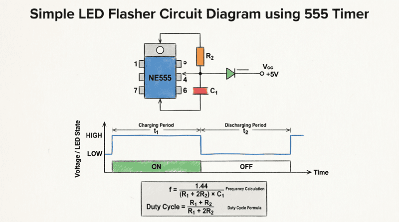
The flash rate (frequency) and duty cycle are determined by the values of R1, R2, and C1.
Frequency Formula:
$$f = \frac{1.44}{(R1 + 2 \times R2) \times C1}$$
Time HIGH (LED ON):
$$t_{HIGH} = 0.693 \times (R1 + R2) \times C1$$
Time LOW (LED OFF):
$$t_{LOW} = 0.693 \times R2 \times C1$$
Total Period:
$$T = t_{HIGH} + t_{LOW} = 0.693 \times (R1 + 2 \times R2) \times C1$$
Duty Cycle:
$$Duty\ Cycle = \frac{t_{HIGH}}{T} \times 100\% = \frac{R1 + R2}{R1 + 2 \times R2} \times 100\%$$
Example Calculation
Design Goal: Create an LED flasher that blinks once per second (1 Hz) with approximately 50% duty cycle.
Given:
- Target frequency: $f = 1\text{ Hz}$
- Choose $C1 = 10\text{ µF} = 10 \times 10^{-6}\text{ F}$
Calculate Total Resistance:
$$R1 + 2 \times R2 = \frac{1.44}{f \times C1} = \frac{1.44}{1 \times 10 \times 10^{-6}} = 144,000\text{ Ω} = 144\text{ kΩ}$$
For 50% Duty Cycle:
We need $R1 \ll R2$. Let’s choose:
- $R1 = 1\text{ kΩ}$
- $R2 = 71.5\text{ kΩ}$ (use standard 68kΩ or 75kΩ)
Verification:
$$f = \frac{1.44}{(1000 + 2 \times 68000) \times 10 \times 10^{-6}} = \frac{1.44}{1.37} \approx 1.05\text{ Hz}$$
This gives us approximately 1 blink per second, which is perfect for a visible flasher.
How do you calculate the flash rate of a 555 timer LED flasher?
The frequency is calculated using: $f = 1.44 / ((R1 + 2 \times R2) \times C1)$, where R1 and R2 are in ohms and C1 is in farads. For a 1 Hz flash rate with a 10µF capacitor, you need a total resistance of approximately 144kΩ.
Transistor-Based Astable Multivibrator
For those who prefer discrete components or want to understand the fundamental principles of oscillation, the transistor astable multivibrator is an excellent alternative to the 555 timer. This classic circuit uses two transistors, four resistors, and two capacitors to create a self-oscillating circuit.
Circuit Operation
The astable multivibrator works on the principle of positive feedback and capacitive coupling. The circuit has no stable state—it continuously flips between two quasi-stable states, causing the LEDs to alternate or a single LED to flash.
Components Required:
- 2 NPN transistors (2N2222, BC547, or similar)
- 2 LEDs (or 1 LED for single flasher)
- 4 resistors (2 base resistors, 2 collector resistors)
- 2 capacitors (timing capacitors)
- 9V battery or DC power supply
Typical Values:
- Collector resistors (R1, R4): 470Ω to 1kΩ
- Base resistors (R2, R3): 10kΩ to 100kΩ
- Timing capacitors (C1, C2): 10µF to 100µF
How It Works
State 1:
- Assume Q1 is ON (saturated) and Q2 is OFF
- LED1 is ON, LED2 is OFF
- Capacitor C1 charges through R2
- When C1 voltage reaches ~0.7V, it turns on Q2
State 2:
- Q2 turns ON, pulling its collector LOW
- This LOW is coupled through C2 to the base of Q1
- Q1 turns OFF
- LED2 is ON, LED1 is OFF
- Capacitor C2 charges through R3
- When C2 voltage reaches ~0.7V, it turns on Q1
This cycle repeats indefinitely, creating oscillation.
Frequency Calculation
The oscillation frequency is determined by the RC time constants:
$$f = \frac{1}{1.38 \times R \times C}$$
Where:
- $R$ = Base resistor value (R2 or R3)
- $C$ = Timing capacitor value (C1 or C2)
For symmetrical oscillation (50% duty cycle), use equal values:
- $R2 = R3$
- $C1 = C2$
Example:
With $R = 47\text{ kΩ}$ and $C = 10\text{ µF}$:
$$f = \frac{1}{1.38 \times 47000 \times 10 \times 10^{-6}} = \frac{1}{0.6486} \approx 1.54\text{ Hz}$$
This produces approximately 1.5 flashes per second.
Advantages of Transistor Design
- Educational Value: Teaches fundamental transistor operation and feedback principles
- Component Availability: Transistors and passive components are universally available
- Customization: Easy to modify for different flash rates or patterns
- No IC Required: Useful when 555 timers are unavailable
- Dual LED Operation: Can easily drive two alternating LEDs
LED Flasher Using Logic Gates
Digital logic gates, particularly inverters (NOT gates) or NAND gates, can also be configured to create LED flasher circuits. This approach is popular in digital electronics courses and when working with CMOS logic families like the 4000 series or 74HC series.
CMOS Inverter Oscillator
A simple CMOS inverter (such as the 4049 or 74HC04) can be configured as an astable multivibrator using a resistor and capacitor.
Circuit Configuration:
- Connect the inverter output to its input through a resistor (R)
- Connect a capacitor (C) from the input to ground
- The output will oscillate between HIGH and LOW
Frequency:
$$f \approx \frac{1}{2.2 \times R \times C}$$
Advantages:
- Very simple (only 1 IC, 1 resistor, 1 capacitor)
- Low power consumption (CMOS)
- Can cascade multiple inverters for complex patterns
NAND Gate Astable Multivibrator
Using a quad NAND gate IC (such as 4011 or 74HC00), you can create a more stable oscillator.
Configuration:
- Use two NAND gates in a feedback configuration
- Similar to the transistor multivibrator but with digital logic
- Provides better noise immunity
Practical Design Considerations
LED Current Limiting
Regardless of the flasher circuit type, always use a current-limiting resistor in series with the LED to prevent damage.
Calculation:
$$R_{LED} = \frac{V_{supply} – V_{LED}}{I_{LED}}$$
Where:
- $V_{supply}$ = Supply voltage (e.g., 9V)
- $V_{LED}$ = LED forward voltage (1.8V for red, 3.3V for blue/white)
- $I_{LED}$ = Desired LED current (10-20mA typical)
Example:
For a red LED ($V_f = 1.8V$) at 15mA with 9V supply:
$$R_{LED} = \frac{9 – 1.8}{0.015} = \frac{7.2}{0.015} = 480\text{ Ω}$$
Use a standard 470Ω or 560Ω resistor.
Power Supply Considerations
Voltage Range:
- 555 Timer: 4.5V to 15V (bipolar), 3V to 15V (CMOS)
- Transistor circuits: 3V to 12V typical
- CMOS logic: 3V to 15V (4000 series), 2V to 6V (74HC series)
Battery Life:
For battery-operated flashers, consider:
- Using high-efficiency LEDs (lower current)
- Increasing flash interval (lower frequency)
- Using CMOS components (lower quiescent current)
- Adding a sleep mode or duty cycling
Adjusting Flash Rate
Variable Flash Rate:
To make the flash rate adjustable, replace one of the timing resistors with a potentiometer (variable resistor).
Example:
Replace R2 in a 555 circuit with a 100kΩ potentiometer. This allows you to adjust the flash rate from approximately 0.5 Hz to 5 Hz by turning the knob.
Multiple LED Patterns
Sequential Flashing:
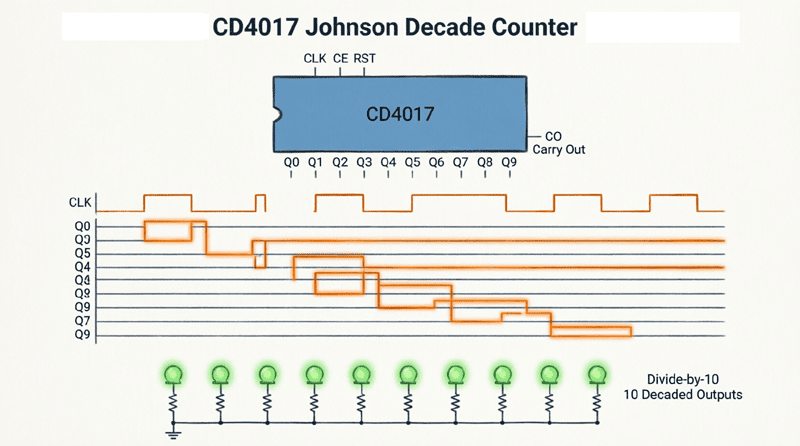
Use a 555 timer to clock a counter IC (such as 4017 Johnson counter or 74HC595 shift register) to create sequential LED patterns.
Alternating LEDs:
Use the transistor astable multivibrator with two LEDs to create an alternating “chase” effect.
Random Flashing:
Add noise or use a microcontroller to create pseudo-random flashing patterns for decorative effects.
Advanced LED Flasher Applications
Emergency Warning Lights
LED flashers are the heart of emergency vehicle warning systems, construction site warning lights, and hazard indicators.
Requirements:
- High brightness LEDs
- Fast flash rate (2-4 Hz)
- High reliability
- Weather resistance
- Multiple LED arrays
Design Tips:
- Use high-power LEDs with proper heat sinking
- Implement redundant circuits for reliability
- Add current regulation for consistent brightness
- Use sealed enclosures for outdoor use
Decorative and Artistic Lighting
LED flashers are popular in:
- Holiday decorations (Christmas lights, Halloween props)
- Art installations
- Stage lighting effects
- Architectural lighting
Techniques:
- Chasing lights: Multiple LEDs flashing in sequence
- Fading effects: Use PWM (Pulse Width Modulation) for smooth brightness transitions
- Color changing: Use RGB LEDs with multiple flasher circuits
- Synchronization: Multiple flashers synchronized for large displays
Communication and Signaling
LED flashers can transmit information through light:
Morse Code:
Program a microcontroller or use a 555 timer with variable timing to flash Morse code messages.
Optical Communication:
Use fast LED flashers (kHz range) to transmit data through visible light communication (VLC) or Li-Fi systems.
Status Indicators:
- Slow flash (0.5 Hz): Standby or idle mode
- Fast flash (2 Hz): Active or processing
- Very fast flash (10 Hz): Error or warning
- Solid ON: Power on or critical state
Biological and Psychological Applications
Strobe Lights:
High-speed LED flashers (10-20 Hz) can create strobe effects for:
- Entertainment (dance clubs, concerts)
- Scientific experiments (visual perception studies)
- Medical applications (phototherapy)
️ Warning: Strobe lights can trigger seizures in people with photosensitive epilepsy. Always include warnings and avoid frequencies between 5-30 Hz in public installations.
Troubleshooting Common LED Flasher Problems
LED Doesn’t Flash
Possible Causes:
- Incorrect wiring: Double-check all connections against the schematic
- LED polarity reversed: Ensure anode (+) and cathode (-) are correct
- Power supply issues: Verify voltage with a multimeter
- Component values wrong: Check resistor and capacitor values
- IC damaged: Try replacing the 555 timer or transistors
Flash Rate Too Fast or Too Slow
Solutions:
- Increase capacitor value to slow down
- Decrease capacitor value to speed up
- Adjust resistor values (increase R to slow, decrease R to speed up)
- Check for capacitor leakage (old electrolytic capacitors)
LED Too Dim
Solutions:
- Decrease current-limiting resistor value (but don’t exceed LED max current)
- Increase supply voltage (within component ratings)
- Use high-efficiency LEDs
- Check for voltage drops in wiring
Irregular or Unstable Flashing
Causes:
- Loose connections
- Capacitor leakage or degradation
- Power supply noise
- Component values drifting with temperature
Solutions:
- Solder all connections securely
- Replace old electrolytic capacitors
- Add decoupling capacitors (0.1µF) near IC power pins
- Use temperature-stable components
LED flasher circuits are a cornerstone of electronics education and practical design. From the versatile 555 timer to the fundamental transistor astable multivibrator and digital logic gate oscillators, there are numerous ways to create blinking LED circuits suitable for any application.
Key takeaways from this guide include:
- 555 Timer Dominance: The 555 timer in astable mode remains the most popular and versatile solution, offering easy frequency adjustment and reliable operation.
- Timing Calculations: Understanding the formulas $f = 1.44 / ((R1 + 2R2) \times C1)$ for 555 timers and $f = 1 / (1.38 \times R \times C)$ for transistor multivibrators is essential for precise design.
- Component Selection: Proper selection of resistors, capacitors, and current-limiting components ensures reliable operation and protects the LEDs.
- Versatility: LED flashers can be simple single-LED blinkers or complex multi-LED pattern generators, serving applications from emergency warnings to artistic installations.
- Practical Considerations: Power supply voltage, LED current limiting, duty cycle, and component tolerances all affect circuit performance and must be carefully considered.
Whether you’re building your first electronics project or designing a sophisticated warning system, the LED flasher circuit provides an excellent platform for learning about timing, oscillation, and sequential logic. The skills and knowledge gained from designing these circuits form the foundation for more advanced topics in digital electronics, embedded systems, and signal processing.
As you continue your electronics journey, remember that the LED flasher is more than just a blinking light—it’s a gateway to understanding the fundamental principles of electronic oscillation and timing that underpin virtually all modern digital systems.