7-Segment Display Counter
7-Segment Display Counter: Complete Guide to Digital Display Design
Introduction to 7-Segment Display Counters
The 7-segment display counter is one of the most ubiquitous and recognizable interfaces in digital electronics. From digital clocks and calculators to microwave ovens and industrial control panels, 7-segment displays provide a simple, cost-effective way to show numerical information in a human-readable format.
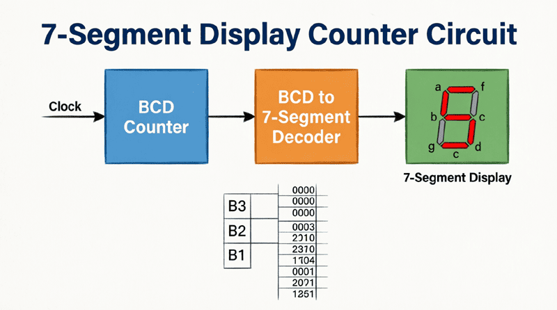
A 7-segment display counter combines three essential components:
- Counter Circuit: Generates the binary or BCD count sequence
- Decoder/Driver: Converts binary/BCD to 7-segment format
- 7-Segment Display: Visually presents the decimal digits
This powerful combination allows digital systems to count events, display time, show measurements, and provide user feedback in a clear, intuitive manner. Whether you’re building a simple frequency counter or a complex digital clock, understanding how to interface counters with 7-segment displays is an essential skill.
This comprehensive guide will explore every aspect of 7-segment display counters, from the basic structure of 7-segment displays to advanced multiplexing techniques for multi-digit systems. We will examine decoder ICs like the 74LS47 and 74LS48, discuss common-anode versus common-cathode configurations, and provide practical circuit designs for single and multi-digit counters.
What is a 7-Segment Display Counter?
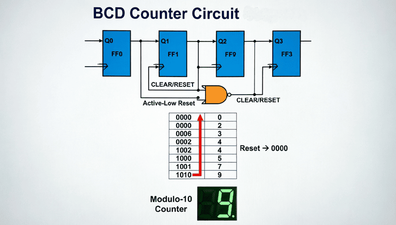
A 7-segment display counter is a digital circuit that counts pulses and displays the result on a 7-segment LED display. It consists of a counter (like 74LS90), a BCD-to-7-segment decoder (like 74LS47), and a 7-segment display. The counter generates BCD output, the decoder converts it to segment signals, and the display shows the decimal digit.
Understanding 7-Segment Displays
Structure and Segments
A 7-segment display consists of seven LED segments arranged in a rectangular pattern that can form the digits 0-9 (and some letters). The segments are labeled a, b, c, d, e, f, g:
     a
    ---
 f |   | b
    -g-
 e |   | c
    ---
     d
Segment Activation Patterns:
| Digit | Segments ON | a | b | c | d | e | f | g |
|---|---|---|---|---|---|---|---|---|
| 0 | a,b,c,d,e,f | 1 | 1 | 1 | 1 | 1 | 1 | 0 |
| 1 | b,c | 0 | 1 | 1 | 0 | 0 | 0 | 0 |
| 2 | a,b,d,e,g | 1 | 1 | 0 | 1 | 1 | 0 | 1 |
| 3 | a,b,c,d,g | 1 | 1 | 1 | 1 | 0 | 0 | 1 |
| 4 | b,c,f,g | 0 | 1 | 1 | 0 | 0 | 1 | 1 |
| 5 | a,c,d,f,g | 1 | 0 | 1 | 1 | 0 | 1 | 1 |
| 6 | a,c,d,e,f,g | 1 | 0 | 1 | 1 | 1 | 1 | 1 |
| 7 | a,b,c | 1 | 1 | 1 | 0 | 0 | 0 | 0 |
| 8 | a,b,c,d,e,f,g | 1 | 1 | 1 | 1 | 1 | 1 | 1 |
| 9 | a,b,c,d,f,g | 1 | 1 | 1 | 1 | 0 | 1 | 1 |
Display Types: Common Anode vs. Common Cathode
Common Anode (CA):
- All LED anodes connected together to VCC (+5V)
- Segments turn ON when driven LOW (0)
- Requires active-LOW decoder (like 74LS47)
- Current flows from VCC → segment → decoder (sink)
Common Cathode (CC):
- All LED cathodes connected together to GND
- Segments turn ON when driven HIGH (1)
- Requires active-HIGH decoder (like 74LS48)
- Current flows from decoder (source) → segment → GND
Choosing Between CA and CC:
- Common Anode: More common, compatible with TTL logic (74LS47)
- Common Cathode: Compatible with CMOS logic (74LS48), better for microcontroller interfaces
Current Limiting
Each segment requires a current-limiting resistor to prevent damage:
Calculation:
$$R = \frac{V_{supply} – V_{LED}}{I_{LED}}$$
Where:
- $V_{supply}$ = Supply voltage (typically 5V)
- $V_{LED}$ = LED forward voltage (1.8-2.2V for red, 3.0-3.6V for blue/white)
- $I_{LED}$ = Desired current (10-20mA typical)
Example (Common Anode, Red LED):
$$R = \frac{5V – 1.8V}{0.015A} = \frac{3.2V}{0.015A} = 213\Omega$$
Use standard value: 220Ω or 330Ω
What’s the difference between common anode and common cathode 7-segment displays?
In common anode displays, all LED anodes connect to VCC and segments turn ON with LOW signals (use 74LS47 decoder). In common cathode displays, all cathodes connect to GND and segments turn ON with HIGH signals (use 74LS48 decoder). The choice determines which decoder IC you need.
BCD to 7-Segment Decoder/Driver ICs
The bridge between binary/BCD counters and 7-segment displays is the BCD to 7-segment decoder/driver IC. These chips accept a 4-bit BCD input and generate the appropriate signals to illuminate the correct segments.
74LS47 (Common Anode Decoder)
The 74LS47 is the most popular decoder for common anode displays.
Pin Configuration (16-pin DIP):
- Pins 7, 1, 2, 6: BCD inputs (A, B, C, D where A=LSB, D=MSB)
- Pins 13, 12, 11, 10, 9, 15, 14: Segment outputs (a, b, c, d, e, f, g) – Active LOW
- Pin 3: Lamp Test (LT) – Active LOW (tests all segments)
- Pin 4: Blanking Input/Ripple Blanking Output (BI/RBO)
- Pin 5: Ripple Blanking Input (RBI)
- Pin 16: VCC (+5V)
- Pin 8: GND
Operation:
- Apply BCD code (0000-1001) to inputs A-D
- Outputs go LOW to illuminate corresponding segments
- Invalid inputs (1010-1111) produce blank or special patterns
Special Features:
- Lamp Test (LT): When LOW, all segments turn ON (tests display)
- Blanking Input (BI): When LOW, all segments turn OFF
- Ripple Blanking: Suppresses leading zeros in multi-digit displays
74LS48 (Common Cathode Decoder)
The 74LS48 is designed for common cathode displays.
Key Differences from 74LS47:
- Outputs: Active HIGH (source current)
- Current: Sources current to segments (instead of sinking)
- Internal Resistors: Some versions include current-limiting resistors
Pin Configuration:
- Same pinout as 74LS47
- Segment outputs are active HIGH
- Compatible with common cathode displays
Truth Table (74LS47/48)
| D | C | B | A | a | b | c | d | e | f | g | Display |
|---|---|---|---|---|---|---|---|---|---|---|---|
| 0 | 0 | 0 | 0 | 0 | 0 | 0 | 0 | 0 | 0 | 1 | 0 |
| 0 | 0 | 0 | 1 | 1 | 0 | 0 | 1 | 1 | 1 | 1 | 1 |
| 0 | 0 | 1 | 0 | 0 | 0 | 1 | 0 | 0 | 1 | 0 | 2 |
| 0 | 0 | 1 | 1 | 0 | 0 | 0 | 0 | 1 | 1 | 0 | 3 |
| 0 | 1 | 0 | 0 | 1 | 0 | 0 | 1 | 1 | 0 | 0 | 4 |
| 0 | 1 | 0 | 1 | 0 | 1 | 0 | 0 | 1 | 0 | 0 | 5 |
| 0 | 1 | 1 | 0 | 0 | 1 | 0 | 0 | 0 | 0 | 0 | 6 |
| 0 | 1 | 1 | 1 | 0 | 0 | 0 | 1 | 1 | 1 | 1 | 7 |
| 1 | 0 | 0 | 0 | 0 | 0 | 0 | 0 | 0 | 0 | 0 | 8 |
| 1 | 0 | 0 | 1 | 0 | 0 | 0 | 0 | 1 | 0 | 0 | 9 |
Note: For 74LS47, 0 = ON (active LOW), 1 = OFF. For 74LS48, opposite.
Single-Digit BCD Counter with 7-Segment Display
Complete Circuit Design
Let’s design a complete single-digit counter that counts from 0 to 9 and displays the result on a 7-segment display.
Components Required:
- 74LS90 (BCD counter)
- 74LS47 (BCD to 7-segment decoder)
- Common anode 7-segment display
- 7 × 330Ω resistors (current limiting)
- Push-button switch (clock input)
- 10kΩ pull-down resistor
- 5V power supply
Circuit Connections:
74LS90 (Counter):
- Pin 14 (VCC) → +5V
- Pin 7 (GND) → GND
- Pin 2, 3 (R0) → GND (disable reset)
- Pin 6, 7 (R9) → GND (disable set)
- Pin 12 (QA) → Pin 1 (CLK B) [BCD configuration]
- Pin 14 (CLK A) → Clock input (push-button)
- Pins 12, 9, 8, 11 (QA, QB, QC, QD) → Decoder inputs
74LS47 (Decoder):
- Pin 16 (VCC) → +5V
- Pin 8 (GND) → GND
- Pin 7 (A) → QA from 74LS90
- Pin 1 (B) → QB from 74LS90
- Pin 2 (C) → QC from 74LS90
- Pin 6 (D) → QD from 74LS90
- Pin 3 (LT) → +5V (disable lamp test)
- Pin 4 (BI/RBO) → +5V (disable blanking)
- Pin 5 (RBI) → +5V (disable ripple blanking)
- Pins 13, 12, 11, 10, 9, 15, 14 (a-g) → Display segments through 330Ω resistors
7-Segment Display (Common Anode):
- Common anode pin → +5V
- Segment pins a-g → 74LS47 outputs through 330Ω resistors
Clock Input:
- Push-button switch between CLK A and +5V
- 10kΩ pull-down resistor from CLK A to GND
- Each button press advances the counter
Operation
- Initial State: Counter at 0000, display shows “0”
- Button Press: Clock pulse advances counter to 0001
- Display Update: 74LS47 decodes 0001, activates segments b and c
- Visual: Display shows “1”
- Continue: Each press advances: 0→1→2→3→4→5→6→7→8→9→0
Current Calculation
Per Segment:
$$I_{segment} = \frac{5V – 1.8V}{330\Omega} = \frac{3.2V}{330\Omega} = 9.7mA$$
Maximum Current (digit “8” – all segments ON):
$$I_{total} = 7 \times 9.7mA = 67.9mA$$
Ensure the 74LS47 can sink this current (typical: 80mA max).
How do you connect a 74LS90 counter to a 7-segment display?
Connect the 74LS90 outputs (QA, QB, QC, QD) to the 74LS47 inputs (A, B, C, D). Then connect the 74LS47 outputs (a-g) through 330Ω resistors to the 7-segment display segments. For common anode displays, use 74LS47; for common cathode, use 74LS48.
Multi-Digit Display Counters
Single-digit counters are useful, but most applications require multiple digits (00-99, 000-999, etc.). There are two main approaches to multi-digit displays: parallel and multiplexed.
Parallel (Non-Multiplexed) Display
The simplest approach is to use a separate counter, decoder, and display for each digit.
2-Digit Counter (00-99):
Components:
- 2 × 74LS90 (counters)
- 2 × 74LS47 (decoders)
- 2 × 7-segment displays
- 14 × 330Ω resistors
Connections:
- Counter 1 (Units):
- Clock: External clock
- QA to CLK B (BCD config)
- QD to Counter 2 clock input
- Counter 2 (Tens):
- Clock: QD from Counter 1
- QA to CLK B
- Outputs to Decoder 2
- Decoders and Displays:
- Each counter → its own decoder → its own display
Advantages:
- Simple design
- No flicker
- Bright displays
- Easy to troubleshoot
Disadvantages:
- Many components (expensive)
- High power consumption
- Large PCB size
- Not scalable beyond 3-4 digits
Multiplexed Display
Multiplexing is a technique that uses time-division to drive multiple displays with fewer components. Instead of keeping all displays ON continuously, we rapidly switch between them, taking advantage of persistence of vision to create the illusion that all digits are lit simultaneously.
Principle of Operation:
- Display digit 1 for 2-5ms
- Turn off digit 1, display digit 2 for 2-5ms
- Turn off digit 2, display digit 3 for 2-5ms
- Repeat continuously (refresh rate: 60-100Hz)
Advantages:
- Fewer decoder ICs (one decoder for all digits)
- Lower power consumption
- Reduced component count
- Scalable to many digits
- Lower cost
Disadvantages:
- More complex control logic
- Requires refresh circuitry
- Slightly dimmer displays
- Potential flicker if refresh rate too low
2-Digit Multiplexed Counter Design
Components:
- 2 × 74LS90 (counters)
- 1 × 74LS47 (decoder – shared)
- 2 × 7-segment displays (common anode)
- 7 × 330Ω resistors (shared)
- 2 × NPN transistors (2N2222) for digit selection
- 2 × 1kΩ resistors (base resistors)
- 555 timer (for multiplexing clock)
Circuit Architecture:
Counters:
- Counter 1 (Units): Clock input, QA→CLK B, QD→Counter 2 clock
- Counter 2 (Tens): QA→CLK B
- Both counters’ outputs connected together (QA→QA, QB→QB, etc.)
Shared Decoder:
- Single 74LS47
- Inputs connected to both counters’ outputs
- Outputs (a-g) connected to both displays’ segments
Digit Selection:
- Display 1 common anode → Transistor 1 collector
- Display 2 common anode → Transistor 2 collector
- Transistor emitters → +5V
- Transistor bases → Multiplexing control signals
Multiplexing Control:
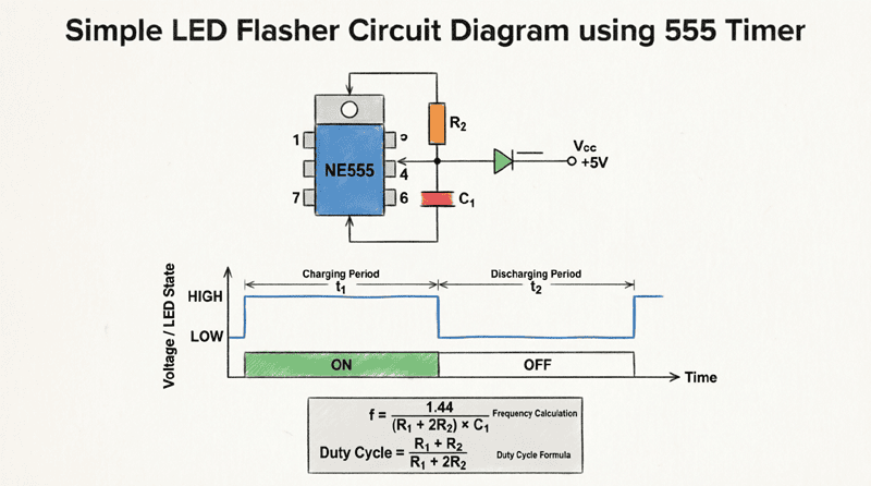
- 555 timer in astable mode (1-2 kHz)
- Output drives a flip-flop or counter
- Flip-flop outputs control transistor bases
- Alternates between Display 1 and Display 2
Operation:
- Phase 1 (2.5ms):
- Transistor 1 ON, Transistor 2 OFF
- Display 1 active, Display 2 off
- Counter 1 outputs on decoder inputs
- Display shows units digit
- Phase 2 (2.5ms):
- Transistor 1 OFF, Transistor 2 ON
- Display 1 off, Display 2 active
- Counter 2 outputs on decoder inputs
- Display shows tens digit
- Repeat: Cycle repeats at 200-400Hz refresh rate
Refresh Rate Calculation:
For 2-digit display:
- Time per digit: 2.5ms
- Total cycle: 5ms
- Refresh rate: $f = \frac{1}{0.005s} = 200Hz$
This is well above the flicker fusion threshold (~60Hz), so the display appears steady.
Current Considerations in Multiplexing
In multiplexed displays, each digit is only ON for a fraction of the time. To maintain brightness, we can increase the segment current during the ON time.
Duty Cycle:
$$Duty\ Cycle = \frac{1}{Number\ of\ Digits}$$
For 2-digit display: Duty Cycle = 1/2 = 50%
Peak Current:
$$I_{peak} = \frac{I_{average}}{Duty\ Cycle}$$
For 10mA average:
$$I_{peak} = \frac{10mA}{0.5} = 20mA$$
This is within the safe operating range for most LEDs.
Advanced Display Techniques
3-Digit and 4-Digit Multiplexed Counters
The multiplexing principle extends to any number of digits.
3-Digit Counter (000-999):
- 3 × 74LS90 counters
- 1 × 74LS47 decoder
- 3 × 7-segment displays
- 3 × transistors for digit selection
- 3-bit counter or decoder for multiplexing control
4-Digit Counter (0000-9999):
- 4 × 74LS90 counters
- 1 × 74LS47 decoder
- 4 × 7-segment displays
- 4 × transistors
- 2-bit binary counter (74LS93) for multiplexing
Multiplexing Control for 4 Digits:
- Use 74LS93 (MOD-4 counter)
- Clock: 1-2 kHz
- Outputs Q0, Q1 control 2-to-4 decoder (74LS139)
- Decoder outputs drive transistor bases
- Sequentially activates Display 1, 2, 3, 4
Using Display Driver ICs
Instead of discrete multiplexing, you can use dedicated display driver ICs that handle everything:
74LS470/471:
- BCD counter with built-in 7-segment decoder
- Simplifies design
- More expensive
MAX7219:
- Serial interface (SPI)
- Drives up to 8 digits
- Built-in multiplexing
- Programmable brightness
- Ideal for microcontroller projects
CD4511:
- BCD to 7-segment latch/decoder
- CMOS technology
- Lower power consumption
- Built-in latch
Microcontroller-Based Counters
Modern designs often use microcontrollers (Arduino, PIC, AVR) to handle counting and display:
Advantages:
- Single IC replaces counters, decoders, and multiplexing logic
- Programmable counting sequences
- Easy to add features (buttons, alarms, etc.)
- Compact design
Example (Arduino):
int digitPins[] = {2, 3, 4, 5};  // Digit select pins
int segmentPins[] = {6, 7, 8, 9, 10, 11, 12};  // a-g pins
int count = 0;

void setup() {
  // Set all pins as outputs
  for (int i = 0; i < 4; i++) pinMode(digitPins[i], OUTPUT);
  for (int i = 0; i < 7; i++) pinMode(segmentPins[i], OUTPUT);
}

void loop() {
  count++;
  if (count > 9999) count = 0;
  displayNumber(count);
  delay(1000);  // Update every second
}

void displayNumber(int num) {
  int digits[4];
  digits[0] = num % 10;
  digits[1] = (num / 10) % 10;
  digits[2] = (num / 100) % 10;
  digits[3] = (num / 1000) % 10;

  for (int i = 0; i < 4; i++) {
    digitalWrite(digitPins[i], HIGH);  // Activate digit
    displayDigit(digits[i]);
    delay(3);  // Display for 3ms
    digitalWrite(digitPins[i], LOW);  // Turn off digit
  }
}
Practical Applications
1. Digital Clock
A complete digital clock requires:
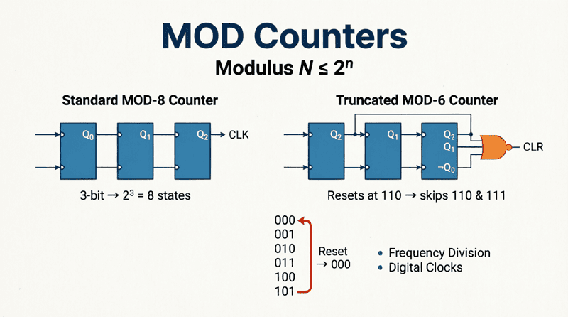
- Seconds: 2-digit MOD-60 counter (multiplexed)
- Minutes: 2-digit MOD-60 counter (multiplexed)
- Hours: 2-digit MOD-12 or MOD-24 counter (multiplexed)
- Timebase: 1 Hz clock (from 555 timer or crystal oscillator)
Total: 6 digits, 3 × 74LS90 pairs, 3 × 74LS47 decoders (or multiplexed)
2. Frequency Counter
Measures input signal frequency:
- Gate input signal for exactly 1 second
- Count pulses using cascaded BCD counters
- Display count (frequency in Hz)
- Use 4-6 digits for MHz range
3. Digital Multimeter
Displays voltage, current, resistance:
- ADC converts analog to digital
- BCD output drives 7-segment displays
- 3.5 or 4.5 digit resolution common
- Multiplexed display for compact design
4. Production Counter
Counts items on assembly line:
- Sensor generates pulse per item
- Counter increments
- Display shows total count
- Reset button for new batch
- Optional: Alarm at preset count
5. Parking Lot Counter
Tracks cars in parking lot:
- Entry sensor: UP counter
- Exit sensor: DOWN counter
- Display shows available spaces
- Full indicator when count = 0
Troubleshooting 7-Segment Display Counters
Common Problems and Solutions
Problem 1: Display Shows Garbage or Random Segments
Causes:
- Loose connections
- Invalid BCD input (1010-1111)
- Faulty decoder IC
- Wrong display type (CA vs CC mismatch)
Solutions:
- Check all connections with multimeter
- Verify counter resets properly at 9
- Test decoder with known BCD inputs
- Ensure 74LS47 matches common anode display
Problem 2: Display is Dim or Flickering
Causes:
- Insufficient current (resistors too large)
- Low supply voltage
- Multiplexing refresh rate too low
- Weak transistor drivers
Solutions:
- Reduce resistor values (220Ω instead of 330Ω)
- Check power supply voltage (should be 5V)
- Increase multiplexing clock frequency
- Use transistors with higher current gain
Problem 3: Some Segments Don’t Light
Causes:
- Burned-out LED segment
- Open resistor
- Faulty decoder output
- Bad connection
Solutions:
- Test display with direct 5V through resistor
- Check resistor continuity
- Measure decoder output voltage
- Inspect solder joints
Problem 4: Counter Doesn’t Advance
Causes:
- No clock signal
- Clock debouncing issue
- Counter reset stuck active
- Power supply problems
Solutions:
- Verify clock with oscilloscope
- Add debouncing circuit for mechanical switches
- Check reset pins are not floating
- Measure supply voltage at IC pins
7-segment display counters are fundamental building blocks in digital electronics, providing a clear, human-readable interface for numerical information. By combining BCD counters, decoder/driver ICs, and 7-segment displays, you can create everything from simple single-digit counters to complex multi-digit measurement instruments.
Key takeaways from this guide include:
- 7-Segment Structure: Seven LED segments (a-g) arranged to display digits 0-9. Common anode displays require active-LOW signals (74LS47), while common cathode displays require active-HIGH signals (74LS48).
- Decoder ICs: The 74LS47 (common anode) and 74LS48 (common cathode) convert 4-bit BCD to 7-segment format, handling all the complex logic internally.
- Single-Digit Design: A complete counter requires a 74LS90 (counter), 74LS47 (decoder), 7-segment display, and current-limiting resistors (330Ω typical).
- Multi-Digit Displays: Use parallel design for simplicity (separate counter/decoder per digit) or multiplexing for efficiency (shared decoder, time-division display).
- Multiplexing: Rapidly switches between digits (60-200Hz refresh rate) to create the illusion of simultaneous display, reducing component count and power consumption.
- Current Considerations: Calculate resistor values using $R = (V_{supply} – V_{LED}) / I_{LED}$. For multiplexed displays, increase peak current to maintain brightness.
- Applications: Digital clocks, frequency counters, multimeters, production counters, and parking lot systems all rely on 7-segment display counters.
- Modern Alternatives: Microcontrollers and dedicated driver ICs (MAX7219) simplify design and add programmability, but discrete designs remain valuable for learning and specific applications.
Whether you’re building your first digital counter or designing a complex measurement system, understanding 7-segment display counters provides the foundation for creating effective human-machine interfaces. The principles learned here—BCD counting, decoding, multiplexing, and current management—apply to countless digital display applications.
As display technology evolves with LCDs, OLEDs, and graphical displays, 7-segment displays remain relevant due to their simplicity, low cost, high visibility, and ease of implementation. They continue to be the display of choice for applications where clear, numerical information is the primary requirement.